Polarization tomography microscopic imaging device and method
What is Al technical title?
Al technical title is built by PatSnap Al team. It summarizes the technical point description of the patent document.
A microscopic imaging and polarization state technology, applied in the direction of polarization influence characteristics, etc., can solve the problems of inability to obtain target polarization information, incomplete information, misjudgment, etc.
Active Publication Date: 2016-04-20
SOUTH CHINA NORMAL UNIVERSITY
View PDF4 Cites 0 Cited by
Summary
Abstract
Description
Claims
Application Information
AI Technical Summary
This helps you quickly interpret patents by identifying the three key elements:
Problems solved by technology
Method used
Benefits of technology
Problems solved by technology
However, the traditional polarized light imaging technology only uses a certain projection of the polarization state of light as the imaging physical quantity for imaging, and cannot obtain all the polarization information of the target. Or the orientation of the polarizer is different, the obtained images are different, and the obtained information is incomplete. Therefore, it is impossible to judge the change of the target by the change of the image, and even cause misjudgment
Method used
Image
Click on the blue label to locate the original text in one second.
Reading with bidirectional positioning of images and text.
Examples
Embodiment Construction
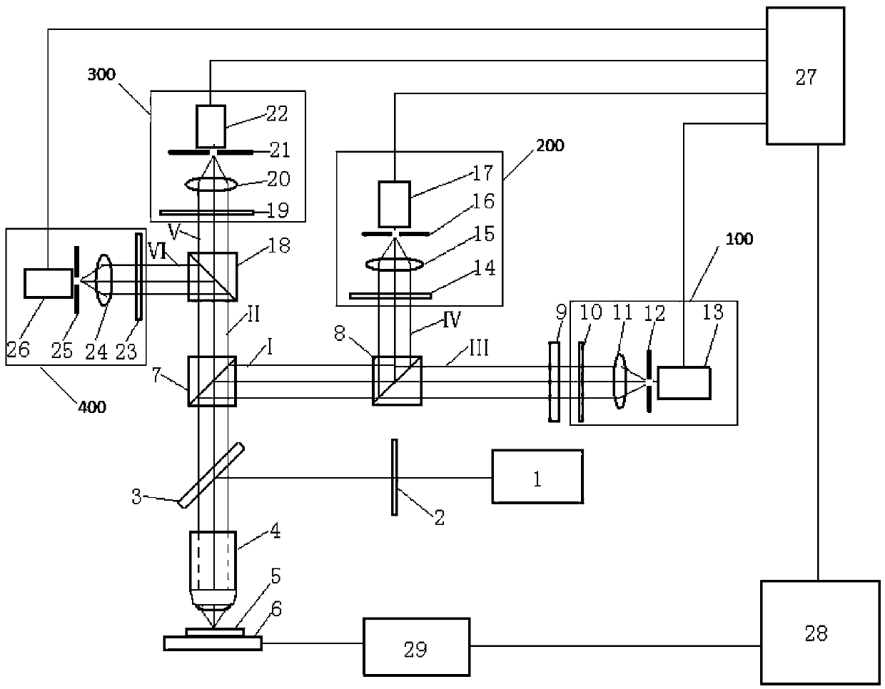
[0040] Reference figure 1 , The present invention provides a polarization tomography microscopic imaging device, including: a laser 1, a polarization generator 2, a half mirror 3, a microscope objective lens 4, a first beam splitter 7, a second beam splitter 8 , Third beam splitter 18, quarter wave plate 9, first Stokes system 100, second Stokes system 200, third Stokes system 300, fourth Stokes system 400, a data acquisition module 27, a computer 28, a driving module 29, and an XY scanning platform 6 for installing the sample 5 to be tested;
[0041] The laser light emitted by the laser 1 is polarized by the polarization generator 2 and is incident on the half mirror 3, and the polarized laser reflected from the half mirror 3 is focused on the test sample 5 through the microscope objective 4 and reflected , The polarized laser light reflected from the tested sample 5 is incident on the first beam splitter 7 through the microscope objective lens 4 and the half mirror 3 in turn, a...
PUM
Abstract
The invention discloses a polarization tomography microscopic imaging device and method. The device comprises: a laser, a polarization generator, a half mirror, a microscopic objective lens, a first beam splitter, a second beam splitter, a third Beam splitter, quarter wave plate, first Stokes system, second Stokes system, third Stokes system, fourth Stokes system, data acquisition module, computer, drive Module and X-Y scanning platform for installing the sample to be tested. The invention can obtain all-round polarization information of the sample to be tested, can detect and microscopically image the polarization states of different layers of the object, and can obtain the stress magnitude and direction of different layers inside the object, material structure, molecular arrangement orientation, refraction Rate, internal stress distribution, surface conductivity distribution, surface roughness and other information, more truly and accurately reflect the information of the measured sample, and can be widely used in the field of polarization measurement.
Description
Technical field [0001] The invention relates to the field of polarization state measurement and polarization state microscopic imaging, in particular to a polarization state tomography microscopic imaging device and method. Background technique [0002] Polarized light imaging technology is widely used in minerals, chemistry, biomedicine, materials and other disciplines. In recent years, polarized light imaging technology has also made important progress in remote sensing imaging. In the process of target imaging and recognition, for targets with the same color and reflection intensity but different materials, their polarization characteristics are often different. These targets are simple The intensity imaging is basically unrecognizable. Polarized light imaging technology obtains the polarization characteristic image of the object by extracting the polarization information of the light beam after interacting with the substance. It records more information than pure intensity i...
Claims
Application Information
Patent Timeline
Application Date:The date an application was filed.
Publication Date:The date a patent or application was officially published.
First Publication Date:The earliest publication date of a patent with the same application number.
Issue Date:Publication date of the patent grant document.
PCT Entry Date:The Entry date of PCT National Phase.
Estimated Expiry Date:The statutory expiry date of a patent right according to the Patent Law, and it is the longest term of protection that the patent right can achieve without the termination of the patent right due to other reasons(Term extension factor has been taken into account ).
Invalid Date:Actual expiry date is based on effective date or publication date of legal transaction data of invalid patent.