
Built-in heat pipe dual-medium heat transfer pipe

A dual medium, heat transfer tube technology, applied in indirect heat exchangers, lighting and heating equipment, etc., can solve problems such as insufficient reliability, and achieve the effect of ensuring heat transfer capacity and improving reliability

Inactive Publication Date: 2013-05-29
山东中和热工科技有限公司
View PDF4 Cites 2 Cited by
  • Summary
  • Abstract
  • Description
  • Claims
  • Application Information

AI Technical Summary

Problems solved by technology

[0004] The present invention aims at the shortcoming of insufficient reliability of heat transfer tubes in existing heat pipe heat exchangers, and provides an efficient and reliable built-in heat pipe dual-medium heat transfer tube. The reliability of the heat transfer tube in the specific application process

Method used


Image

  • Built-in heat pipe dual-medium heat transfer pipe
  • Built-in heat pipe dual-medium heat transfer pipe

Examples


Embodiment Construction

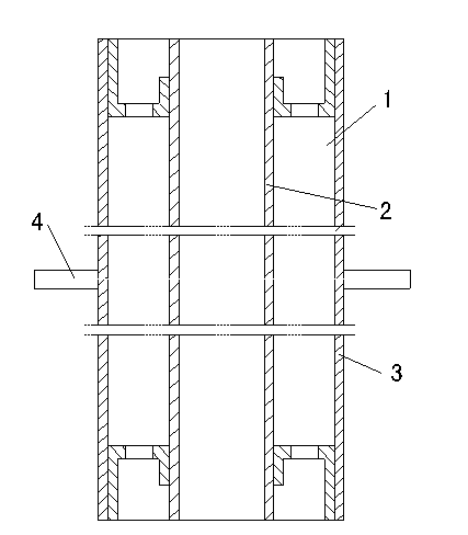
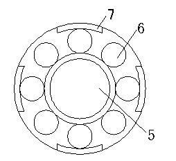
[0012] Such as figure 1 As shown, the dual-medium heat transfer tube with built-in heat pipe of the present invention includes a heat pipe 2 and a sleeve 3 , and the heat pipe 2 is installed in the sleeve 3 through a bracket 1 . The heat pipe 2 and the sleeve pipe 3 are concentric (the axis of the two coincides), so that the distribution of the medium can be even when flowing. Bracket 1 can be used as figure 2 In the structure shown, the bracket 1 is provided with uniform heat pipe installation holes 5 and working fluid channels 6 , the heat pipe installation holes 5 are located in the middle of the bracket 1 , and the working fluid channels 6 are evenly distributed on the periphery of the heat pipe installation holes 5 . A connecting block 7 is arranged on the outside of the bracket 1 , and the bracket 1 is fixed on the end of the casing 3 through the connecting block 7 . The bracket 1 can also adopt a star shape with a heat pipe installation hole 5 in the middle, or other...


PUM


Abstract

Disclosed is a built-in heat pipe dual-medium heat transfer pipe. The built-in heat pipe dual-medium heat transfer pipe comprises sleeve pipes and heat pipes. Each heat pipe is installed in the sleeve pipe through a support. The heat pipes and the sleeve pipes are concentric. A channel is formed between each heat pipe and each sleeve pipe. A first type of medium is injected into each channel. A second type of medium is filled into each heat pipe. The heat transfer pipe is filled with the inner media and the outer media. The first type of medium in each channel between the heat pipe and the sleeve pipe can achieve rapid heat transfer of the inner side and the outer side of each sleeve pipe, and heat transfer effect is guaranteed. The second type of medium in each heat pipe can achieve the heat transfer through evaporation and condensation. Due to the fact that materials and wall thickness of the sleeve pipes are decided according to actual working conditions and free from limitation of the materials of the heat pipes, reliability of the heat transfer pipe is improved greatly, and the built-in heat pipe dual-medium heat transfer pipe can totally meet the safety requirement on a high dangerous occasion that a severe reaction can generate when cold fluid and hot fluid in a heat exchanger are mixed.

Description

technical field [0001] The invention relates to a built-in heat pipe dual-medium heat transfer pipe for efficient and reliable heat transfer, which belongs to the technical field of heat exchange. Background technique [0002] The heat pipe is a heat transfer element with high thermal conductivity. It transfers heat through the evaporation and condensation of the working fluid in the fully enclosed vacuum tube shell. It has extremely high thermal conductivity, good isothermal performance, long-distance heat transfer, and A series of advantages such as temperature control. The heat exchanger with heat pipe as the heat transfer element has the advantages of high heat transfer efficiency, compact structure, small fluid resistance loss, and is beneficial to control dew point corrosion. At present, it has been widely used in metallurgy, chemical industry, oil refining, boiler, ceramics, transportation, textile, machinery and other industries. As an energy-saving equipment for wa...

Claims


Application Information

Patent Timeline
Patent Type & Authority Applications(China)
IPC IPC(8): F28D15/02
Inventor 程林杜文静
Owner 山东中和热工科技有限公司
Learn More