
Circuit and method for measuring stray inductance of current conversion circuit of three-level converter

A commutation circuit and measuring circuit technology, which is applied in the direction of measuring electrical variables, measuring resistance/reactance/impedance, measuring devices, etc., can solve the problems of not including IGBTs, unable to accurately judge IGBTs, etc., and achieve the effect of less variables

Active Publication Date: 2013-05-22
SHANGHAI ELECTRICGROUP CORP
View PDF10 Cites 26 Cited by
  • Summary
  • Abstract
  • Description
  • Claims
  • Application Information

AI Technical Summary

Problems solved by technology

[0003] There are two large commutation circuits and two small commutation circuits in the three-level converter. Since the commutation circuit contains multiple power devices, and the equivalent stray inductance of power devices is an order of magnitude different from that of laminated busbars Therefore, it is not possible to accurately judge the overvoltage level of the IGBT at a certain current level only by relying on the stray inductance value of the laminated busbar.
The traditional stacked busbar stray inductance test method relies on the voltage drop of the device at the moment the IGBT is turned on or off, so the measured results do not include the equivalent stray inductance of the IGBT itself, and the measurement process requires the current to be stable during the voltage drop period. The rate of change, the accuracy of the measurement is closely related to the test conditions

Method used


Image

  • Circuit and method for measuring stray inductance of current conversion circuit of three-level converter
  • Circuit and method for measuring stray inductance of current conversion circuit of three-level converter
  • Circuit and method for measuring stray inductance of current conversion circuit of three-level converter

Examples


Embodiment Construction

[0039] The present invention will be further described below in conjunction with accompanying drawing.

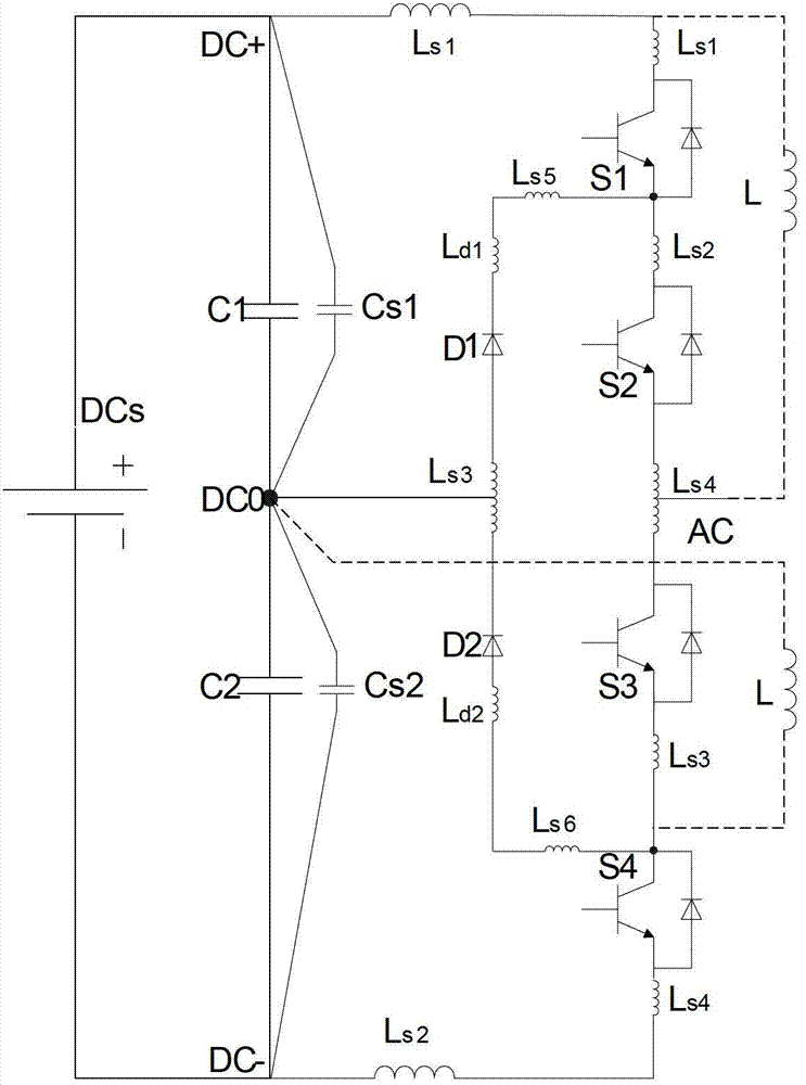
[0040] see figure 1 , one of the measurement circuits of the commutation circuit stray inductance of the three-level converter of the present invention includes the first IGBT S1, the second IGBT S2, the third IGBT S3, the fourth IGBT S4, the first clamping diode D1, the first Two clamping diodes D2, the first resonant capacitor Cs1, the second resonant capacitor Cs2, the first DC support capacitor C1, the second DC support capacitor C2, laminated busbars (not shown in the figure), DC power supply DCs and continued Flow reactor L, where:

[0041] The first IGBT, the second IGBT, the third IGBT and the fourth IGBT are connected in series in the same direction, that is: the emitter of the first IGBT S1 is connected to the collector of the second IGBT S2; the emitter of the second IGBT S2 is connected to the collector of the third IGBT S3 An electrode; the emitter of the thi...


PUM


Abstract

The invention discloses a circuit and a method for measuring stray inductance of a current conversion circuit of a three-level converter. The circuit comprises a first IGBT (insulated gate bipolar transistor), a second IGBT, a third IGBT, a fourth IBGT, a first clamp diode, a second clamp diode, a first resonant capacitor, a second resonant capacitor, a first direct-current support capacitor, a second direct-current support capacitor, a laminated busbar, a direct-current power supply and a freewheel reactor. The method includes forming different freewheel circuits by the freewheel reactor; exerting double pulses to each corresponding IGBT; taking an average value of resonance current frequencies at a turn-on moment and a turn-off moment; and precisely computing the stray inductance of the current conversion circuit by an LC parallel resonance characteristic realized by the resonant capacitors and the stray inductance of the circuit. The circuit and the method have the advantages that actual operation is facilitated, the stray inductance of the current conversion circuit of the three-level converter can be accurately measured, overvoltage levels of a power device under different current grades of the three-level converter can be accurately controlled conveniently, and accordingly establishment of a system control strategy can be guided.

Description

technical field [0001] The invention relates to the application field of power electronics, in particular to a measuring circuit and a measuring method for the stray inductance of a commutation circuit of a three-level converter. Background technique [0002] With the improvement of the power level of the power conversion system and the development of power electronics technology, the power density of the IGBT (insulated gate bipolar transistor) module is getting higher and higher, and the turn-on and turn-off performance is getting better and better, which means that the turn-off current and its slope is getting bigger and bigger. At this time, a voltage will be induced on the stray inductance of the commutation circuit of the three-level converter, and the voltage, together with the DC bus voltage, will be directly added to both ends of the turned-off IGBT, which may exceed the rated voltage of the IGBT and cause the device damage. Therefore, accurately grasping the valu...

Claims


Application Information

Patent Timeline
IPC IPC(8): G01R27/26
Inventor 张鲁华宋小亮尹正兵吴竞之陈国栋董祖毅
Owner SHANGHAI ELECTRICGROUP CORP
Learn More