Control circuit of energy discharging of large magnetic moment magnetorquer

A magnetic torque device and discharge circuit technology, which is applied in the direction of electrical components, output power conversion devices, AC power input conversion to DC power output, etc., can solve the problem of driving circuit operating voltage increase, power supply voltage increase, charging, etc. problem, to achieve the effect of simple and reliable circuit structure, improved service life and wide application range

Active Publication Date: 2013-05-15
BEIJING INST OF CONTROL ENG
View PDF4 Cites 5 Cited by
  • Summary
  • Abstract
  • Description
  • Claims
  • Application Information

AI Technical Summary

Problems solved by technology

The inductance of the large magnetic moment magnetic torque device is about ten H, and the maximum excitation current is several hundred mA. When the energy is discharged, if the current magnetic torque device energy discharge control circuit is still used, the excitation current will be generated to the power supply. The phenomenon of voltage charging causes the power supply voltage to rise. In the worst case, the power supply voltage can be raised to 4 to 5 times the nominal voltage value, which greatly increases the operating voltage of the device connected to the power supply in the drive circuit, causing the device damage
Therefore, the existing technology cannot meet the control requirements of the energy discharge of the large magnetic moment magnetic torque device

Method used


Image

  • Control circuit of energy discharging of large magnetic moment magnetorquer
  • Control circuit of energy discharging of large magnetic moment magnetorquer

Examples


Embodiment Construction

[0012] Below in conjunction with accompanying drawing and specific embodiment the present invention is described in further detail:

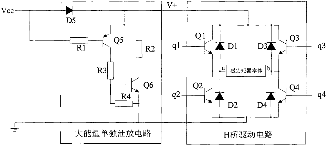
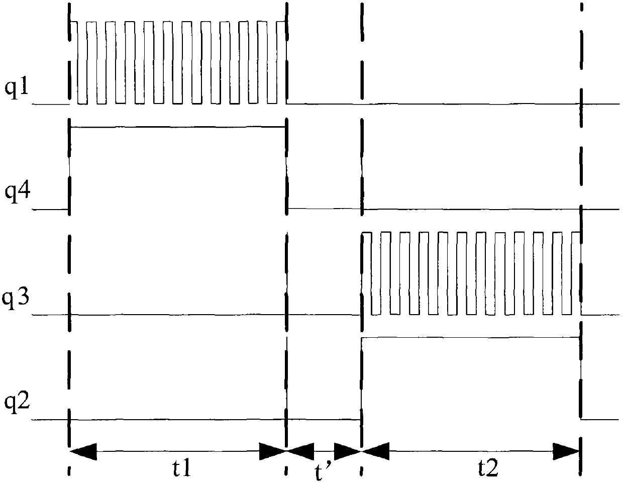
[0013] Such as figure 2 As shown, it is defined that the H-bridge drive circuit works in the positive direction during the t1 period, and the H-bridge drive circuit works in the negative direction during the t2 period, then the t2 period is called the H-bridge drive circuit commutation relative to the t1 period, and the t' period is H During the transition period during the commutation process of the bridge drive circuit, the transistor Q1, the transistor Q2, the transistor Q3 and the transistor Q4 are all in the off state during the t' period. That is to say, the large-energy independent discharge circuit is only used in the t' period, and the large-energy independent discharge circuit does not work in other periods.

[0014] The inductance of the large magnetic moment magnetic torque device is very large, and the stored energy is also large ...


PUM


Abstract

The invention provides a control circuit of energy discharging of a large magnetic moment magnetorquer which comprises a macro-energy independent discharging circuit and an H-bridge drive circuit. When the H-bridge drive circuit is reversed, the macro-energy independent discharging circuit is adopted, and the macro-energy independent discharging circuit transfers most of energy on a magnetorquer body to a power component in the discharging circuit, so that the purpose of the energy discharging is achieved. Under other working states, the H-bridge drive circuit is utilized to discharge the energy of the magnetorquer, power tubes and diodes in the H-bridge circuit and the magnetorquor body are utilized to form a break-over return circuit, and the energy of the magnetorquer body is gradually discharged. The control circuit is simple and reliable in structure, low in power consumption, long in service life, wide in application range, and capable of satisfying requirements of the energy discharging of magnetorquer bodies with different standards.

Description

technical field [0001] The invention relates to a control method for energy discharge, in particular to a control method suitable for energy discharge of a large magnetic moment magnetic torque device. Background technique [0002] The magnetic torquer is one of the executive parts of the spacecraft. It consists of the magnetic torquer body and the drive circuit that provides it with a specific excitation current. It has been widely used in spacecraft attitude control. At present, the output magnetic moment of the magnetic torque device used in the world is usually 5 ~ 1000Am 2 , The magnetic torquer used on domestic spacecraft usually outputs a magnetic moment of 25-400Am 2 . At present, my country is building a space laboratory. The spacecraft developed are very large in size and weight, and the requirements for attitude maneuverability and momentum unloading are very high, resulting in high requirements for the output magnetic moment of the magnetic torque device. There...

Claims


Application Information

Patent Timeline
IPC IPC(8): H02M7/217
Inventor 范佳堃孟海江曹剑徐勤超张磊展毅吴硕
Owner BEIJING INST OF CONTROL ENG
Why Eureka
Try Eureka