Voltage clamping circuit and electronic equipment

A voltage clamping and circuit technology, which is applied in the direction of emergency protection circuit devices, circuit devices, emergency protection circuit devices, etc. for limiting overcurrent/overvoltage, to achieve good protection effect, simple and reliable circuit structure, and good application prospects Effect

Active Publication Date: 2020-02-14
杭州兆鼎科技实业有限公司
View PDF3 Cites 0 Cited by
  • Summary
  • Abstract
  • Description
  • Claims
  • Application Information

AI Technical Summary

Problems solved by technology

[0006] The purpose of the present invention is to provide a voltage clamping circuit and its electronic equipment, which can solve one or more problems existing in the voltage clamping circuit in the prior art

Method used

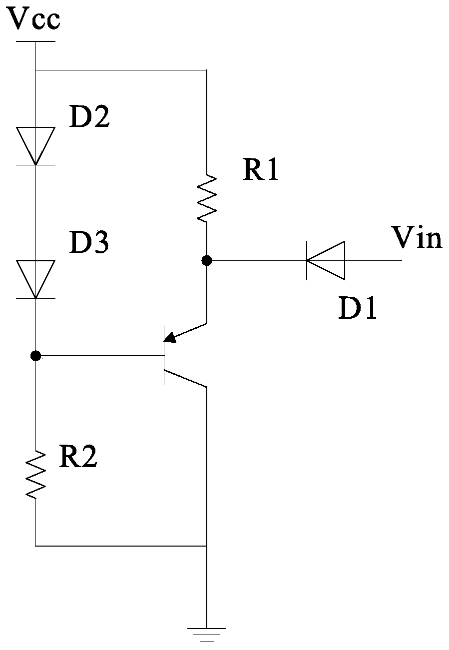
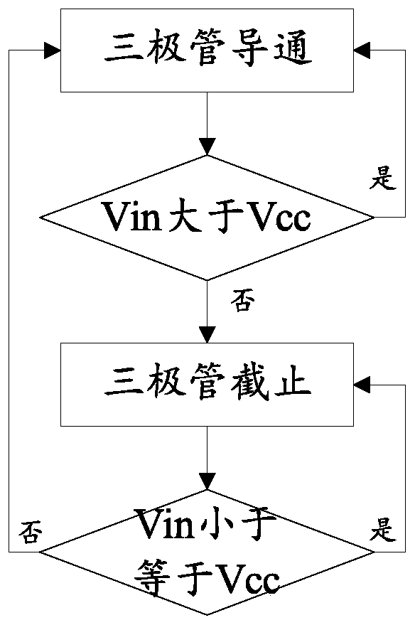

Image

  • Voltage clamping circuit and electronic equipment
  • Voltage clamping circuit and electronic equipment
  • Voltage clamping circuit and electronic equipment

Examples


Embodiment Construction

[0021] In order to make the purpose, technical solutions and advantages of the embodiments of the present invention clearer, the technical solutions in the embodiments of the present invention will be clearly and completely described below in conjunction with the drawings in the embodiments of the present invention. Obviously, the described embodiments It is a part of embodiments of the present invention, but not all embodiments. Based on the embodiments of the present invention, all other embodiments obtained by persons of ordinary skill in the art without making creative efforts belong to the protection scope of the present invention.

[0022] It should be understood that the terminology used in the description of the present invention is for the purpose of describing particular embodiments only and is not intended to be limiting of the present invention. As used in this specification and the appended claims, the singular forms "a", "an" and "the" are intended to include plu...


PUM


Abstract

The invention discloses a voltage clamping circuit. The voltage clamping circuit comprises a protected node and a switching circuit, wherein the first control end of the switching circuit is connectedwith the protected node through a first clamping unit; the second control end of the switching circuit is connected with the direct-current voltage through a second clamping unit; and the first clamping unit and the second clamping unit have a corresponding relationship so as to enable the switching circuit to be conducted when the voltage of the protected node is higher than the direct-current voltage.

Description

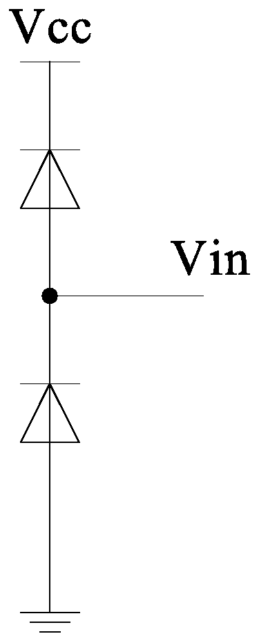
technical field [0001] The invention relates to the technical field of electronic circuits, in particular to a voltage clamping circuit and electronic equipment thereof. Background technique [0002] A voltage clamping circuit refers to a protection circuit that limits the voltage value within a specific range. figure 1 For the traditional dual diode clamp circuit. [0003] Such as figure 1 As shown, the dual-diode clamp circuit consists of two diodes connected in antiparallel. Take advantage of the forward voltage drop present on the diode. At the same time, only one diode can be turned on, while the other is in the cut-off state, so that the forward and reverse voltage drop of the protected node Vin is clamped below the diode forward conduction voltage drop of 0.5-0.7, thus protecting the circuit. Purpose. [0004] Its specific working principle is: when the voltage of the protected node Vin exceeds Vcc+0.7V, the upper diode is turned on. And when the voltage of the ...

Claims


Application Information

Patent Timeline
IPC IPC(8): H02H9/04
CPCH02H9/04
Inventor 罗欣谭黎胡觉远徐范
Owner 杭州兆鼎科技实业有限公司
Why Eureka
Try Eureka