
Lamp lampshade

A lampshade and lamp technology, applied in the field of lighting, can solve the problems of not being able to see clearly the road, roads and vehicles, and prone to traffic accidents, and achieve the effect of uniform light and no glare

Inactive Publication Date: 2013-05-15
DONGGUAN WOOMI POWER TECH
View PDF7 Cites 6 Cited by
  • Summary
  • Abstract
  • Description
  • Claims
  • Application Information

AI Technical Summary

Problems solved by technology

Although the light of street lamps is very soft and can illuminate the road for passers-by, the glare it produces will make people unable to see the road clearly, which is one of the main sources of light pollution in the city; The peripheral upward and outward glare of the effectively illuminated light is stronger and more dazzling than the glare of street lamps. Therefore, when the vehicles cross, the drivers and pedestrians who are illuminated on the opposite side often have blurred vision and cannot see the road and vehicles in front of them clearly. situation, panic often leads to operational errors, and is extremely prone to traffic accidents
[0003] Although the existing lighting equipment also has a design to strengthen the light at the side edge, such as Taiwan Patent Announcement No. M306299 LED ring light source structure, it is mainly fixed with a light guide element above the metal cup body, and the inner edge of the upper end of the light guide element has an arc Surface, and a beveled surface is provided around the lower end of the light guide element to provide the scattered and refracted light generated by the LED light source, which can pass through the mirror curvature inside the light guide element and the curved surface, causing the light to form a critical angle total reflection This phenomenon makes the light scattered around the outside of the light guide element, so as to achieve more light source brightness on the side edge of the LED spotlight source structure. However, the light scattering and the outside of the light guide element cannot provide long-distance illumination.

Method used


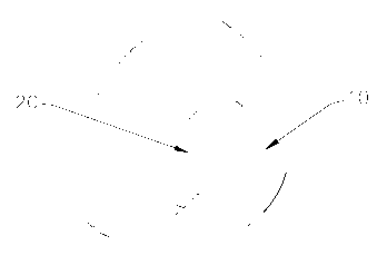
Image

  • Lamp lampshade
  • Lamp lampshade
  • Lamp lampshade

Examples


Embodiment Construction

[0017] In order to further understand the features, technical means, and specific objectives and functions achieved by the present invention, the present invention will be further described in detail below in conjunction with the accompanying drawings and specific embodiments.

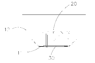
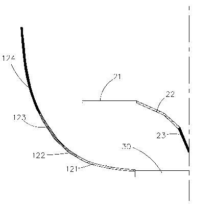
[0018] like Figure 1 to Figure 5 As shown, the lamp shade of the present invention includes a lamp housing 10, a cone 20 and an LED light source 30. The lamp housing 10 is a reflective bowl structure, and the cross section of the lamp housing 10 is roughly "U". Including a base plate 11 and an annular plate 12, the annular plate 12 is surrounded by the base plate 11, the annular plate 12 is provided with a gentle portion 121, a multiple reflection portion 122, a secondary reflection portion 123 and a primary reflection portion 124, The curvatures of the gentle portion 121 , the multiple reflection portion 122 , the secondary reflection portion 123 and the primary reflection portion 124 gradually incre...


PUM


Abstract

The invention discloses a lamp lampshade which comprises a lamp shell, a cone and a light emitting diode (LED) lamp source. The lamp shell is of a reflective bowl structure and comprises an annular plate, the annular plate is provided with a flat portion, a multiple-reflection portion, a second refection portion and a first reflection portion, and the curvature of the flat portion, the multiple-reflection portion, the second reflection portion and the first reflection portion is sequentially increased; and the LED lamp source is fixedly installed on the lamp shell, the cone is fixedly installed above the LED lamp source in a matched mode, the cone is provided with a parallel reflection surface, an overshot light reflection surface and an internal shot light reflection surface, and the horizontal dip angles of the parallel reflection surface, the overshot light reflection surface and the internal shot light reflection surface are sequentially increased. According to the lamp lampshade, the lamp shell is provided with the cone in a matched mode, primary reflection is conducted through the parallel reflection surface, the overshot light reflection surface and the internal shot light reflection surface, the structures of the flat portion, the multiple-reflection portion, the second reflection portion and the first reflection portion are matched to conduct reflection again, and therefore light emitted by the LED lamp source is even and free of the sense of dazzle light.

Description

technical field [0001] The invention relates to the technical field of lighting, in particular to a lampshade for a lamp. Background technique [0002] Street lamps, car headlights and downlights produce effective light beams, but the conical luminous body cannot meet the design requirements due to the surface treatment process, resulting in more than two times of emitted light and uncontrollable light forming dazzling glare. . Although the light of street lamps is very soft and can illuminate the road for passers-by, the glare it produces will make people unable to see the road clearly, which is one of the main sources of light pollution in the city; The peripheral upward and outward glare of the effectively illuminated light is stronger and more dazzling than the glare of street lamps. Therefore, when the vehicles cross, the drivers and pedestrians who are illuminated on the opposite side often have blurred vision and cannot see the road and vehicles in front of them clea...

Claims


Application Information

Patent Timeline
Patent Type & Authority Applications(China)
IPC IPC(8): F21S2/00F21V7/08F21V7/10F21V3/00F21Y101/02
Inventor 颜晓英黄世蔚张元
Owner DONGGUAN WOOMI POWER TECH
Learn More