
Motive power mixing device of hybrid car

A hybrid electric vehicle and power hybrid technology, which is applied to hybrid electric vehicles, power units, air pressure power units, etc., can solve the problems of battery pack charging, increased kinetic energy consumption, and uncoordinated speed

Inactive Publication Date: 2013-05-15
刘培生 +1
View PDF11 Cites 4 Cited by
  • Summary
  • Abstract
  • Description
  • Claims
  • Application Information

AI Technical Summary

Problems solved by technology

[0002] Common hybrid electric vehicles, the combination of oil and electricity systems often have the following situations: 1. Some driving power has been converted several times, resulting in serious energy waste. The gasoline engine is used to drive the generator to generate electricity, and then the electricity generated is used to charge the battery. Then use the battery to drive the motor to work. After several transformations, the efficiency is low, resulting in a waste of fuel and an increase in kinetic energy consumption; The front and rear axles are driven separately, and the speed is uncoordinated, so there is a waste of kinetic energy
2. Repeated installation of generators leads to waste of equipment and increased kinetic energy consumption. The specific manifestation is that A generator is often added when the original internal combustion engine already has a generator, and it is rarely used alone; B is the attachment of the original internal combustion engine. The alternator can only charge a single 12-volt electricity, and cannot charge the battery pack, but it keeps idling when the internal combustion engine is working; 3. The structure is complex, the car body is huge, the cost is high, and the efficiency is low, such as most hybrid cars at home and abroad

Method used


Image

  • Motive power mixing device of hybrid car

Examples


Embodiment Construction

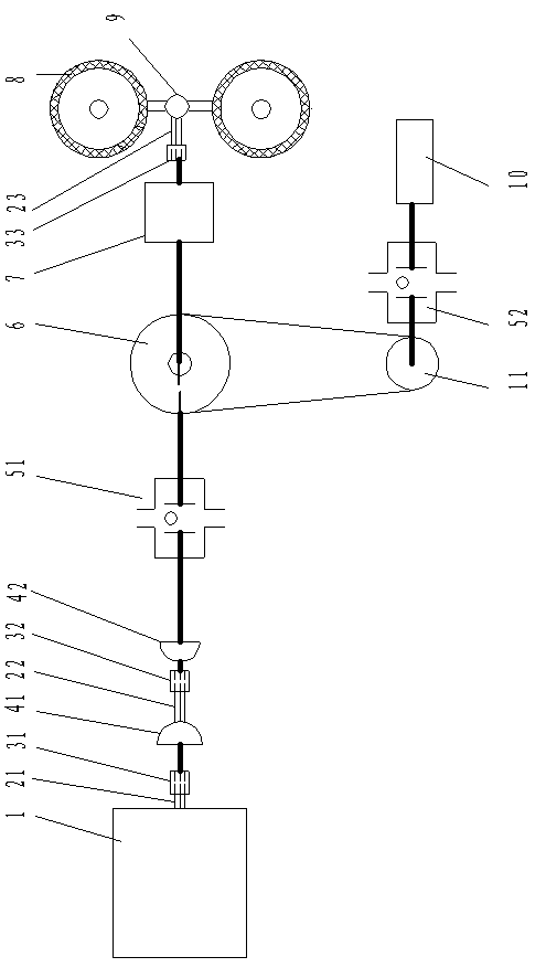
[0016] Combine below figure 1 , describe in detail the concrete working situation that the present invention proposes.

[0017] On the internal-combustion engine power output shaft 21, after the internal-combustion engine and its attached transmission 1, before the differential 9, select an appropriate position, that is, at the original design power interruption place, or at the artificial cut-off place now, the internal-combustion engine (fuel engine) )1 The output shaft is connected with the inner ring (or outer ring) of the overrunning clutch 51 (key fit is available). At this time, the inner ring (or outer ring) of the overrunning clutch 51 rotates in the forward direction to rotate with load and is connected with the internal combustion engine 1 The forward rotation is consistent; the outer ring (or inner ring) of the overrunning clutch 51 cooperates with the part after the disconnection of the output shaft, usually by adding an outer (inner) cover and fixing with a key. ...


PUM


Abstract

The invention relates to a motive power mixing device of a hybrid car. A first single direction clutch is arranged between an output spline shaft of an internal combustion engine and a driven wheel, and a second single direction clutch is arranged between the motor and the driven wheel. Due to the fact that only two sets of new single direction clutches are arranged except for the commonly used vehicle internal combustion engine and the motor, the advantages of a small-displacement fuel engine of high efficiency, oil saving, reasonable structure, mature technology and low cost are sufficiently utilized, the advantages of a direct current motor of large starting torsion and high efficiency and effort saving are sufficiently utilizedto achieve motive power optimization combination, and the motive power mixing device of the hybrid car dose not waste power, and is convenient to operate and capable of achieving motive power optimization combination.

Description

technical field [0001] The invention belongs to the field of production and transformation of hybrid electric vehicles, and in particular relates to a power mixing device of a hybrid electric vehicle. Background technique [0002] Common hybrid electric vehicles, the combination of oil and electricity systems often have the following situations: 1. Some driving power has been converted several times, resulting in serious energy waste. The gasoline engine is used to drive the generator to generate electricity, and then the electricity generated is used to charge the battery. Then use the battery to drive the motor to work. After several transformations, the efficiency is low, resulting in a waste of fuel and an increase in kinetic energy consumption; The front and rear axles are driven separately, and the speed is uncoordinated, so there is a waste of kinetic energy. 2. Repeated installation of generators leads to waste of equipment and increased kinetic energy consumption. ...

Claims


Application Information

Patent Timeline
Patent Type & Authority Applications(China)
IPC IPC(8): B60K6/38B60K6/42
CPCY02T10/62
Inventor 刘培生李海燕
Owner 刘培生
Learn More