
Clamping jaw mechanism

A clamping jaw and frame technology, which is applied in the field of automated machinery and equipment manufacturing, can solve the problems of the hinged clamping jaw mechanism not clamping tightly, the force of the hinged shaft is large, and the service life is affected, so as to prolong the service life and increase the clamping force. , good effect

Active Publication Date: 2013-05-15
苏州凯蒂亚半导体制造设备有限公司
View PDF7 Cites 2 Cited by
  • Summary
  • Abstract
  • Description
  • Claims
  • Application Information

AI Technical Summary

Problems solved by technology

[0003] The existing jaw mechanism is mainly through the hinged left claw and the right claw, and through the principle of leverage, the left claw and the right claw can be clamped when they rotate in opposite directions, and they can be released when they are away from the rotation. Therefore, the hinge shaft is subjected to a large force, which affects its service life. ;In addition, the articulated jaw mechanism sometimes has the problem of not clamping tightly

Method used


Image

  • Clamping jaw mechanism
  • Clamping jaw mechanism
  • Clamping jaw mechanism

Examples


Embodiment

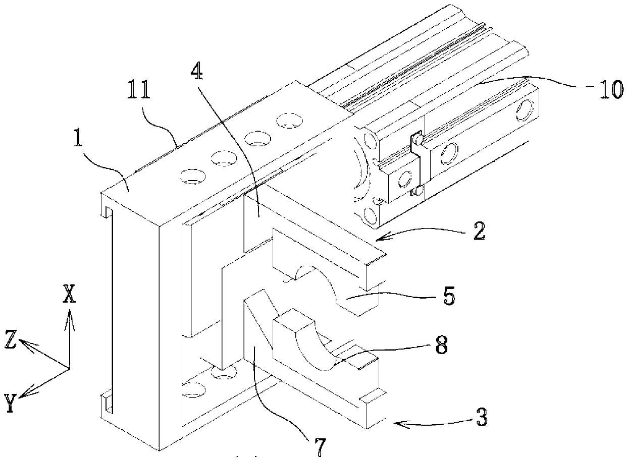
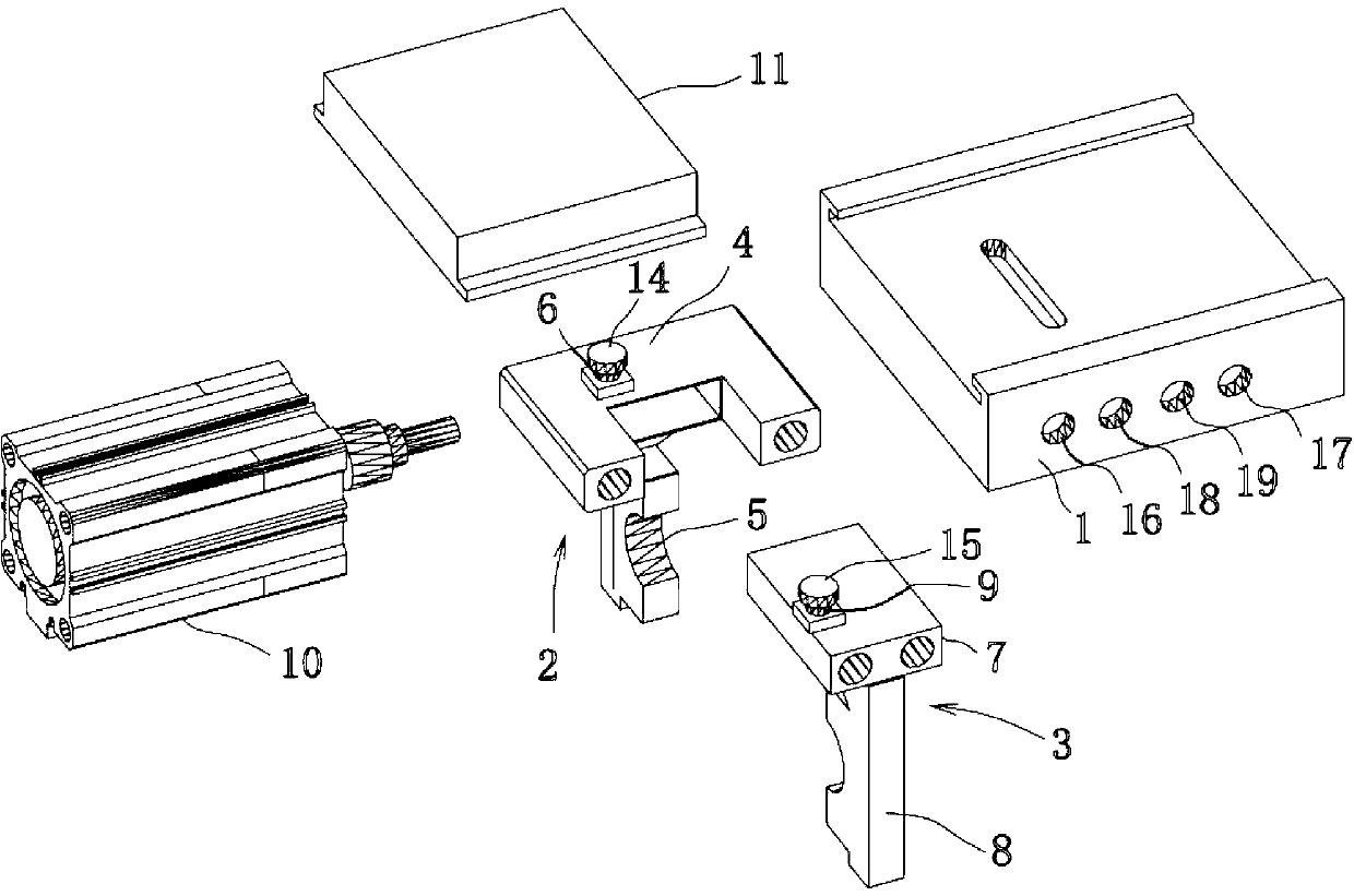
[0025] Example: see attached Figures 1 to 4 As shown, a clamping claw mechanism includes a frame 1, a left claw portion 2 and a right claw portion 3. The left claw portion 2 has a left claw seat 4 on which a left claw 5 is fixed. The claw base 4 is slidably connected with the frame 1 along the X axis, and the left claw base 4 is provided with a left claw slider 6;

[0026] The right claw portion 3 has a right claw seat 7 on which a right claw 8 is fixed, the right claw seat 7 is slidably connected with the frame 1 along the X axis, and a right claw slider is arranged on the right claw seat 7 9;

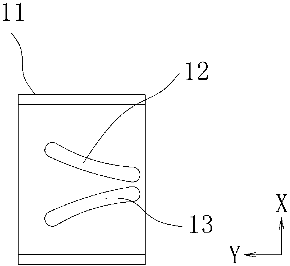
[0027] It also includes a linear drive device 10 and a push slider 11, the push slider 11 is slidably connected with the frame 1 along the Y axis; the push slider 11 is provided with a left slide rail 12 and a right slide rail 13, the The X-axis distance between the left slide rail 12 and the right slide rail 13 gradually increases along the Y-axis direction. The left claw slider 6...


PUM


Abstract

The invention discloses a clamping jaw mechanism. The clamping jaw mechanism comprises a rack, a left jaw part and a right jaw part. The clamping jaw mechanism is characterized in that the left jaw part is provided with a left jaw seat, a left jaw is fixed on the left jaw seat, the left jaw seat is connected with the rack along an X axis in a sliding manner, and a left jaw sliding block is arranged on the left jaw seat; the right jaw part is provided with a right jaw seat, a right jaw is fixed on the right jaw seat, the right jaw seat is connected with the rack along a Y axis in a sliding manner, and a right jaw sliding block is arranged on the right jaw seat; and the clamping jaw mechanism further comprises a linear driving device and a push sliding block, wherein the push sliding block is connected with the rack along the Y axis in a sliding manner and is provided with a left sliding rail and a right sliding rail, the X axial distance of the left sliding rail and the right sliding rail gradually increases along the Y axis, the left jaw sliding block is inserted in the left sliding rail and is connected with the left sliding rail in a sliding and rolling manner, the right jaw sliding block is inserted in the right sliding rail and is connected with the right sliding rail in a sliding and rolling manner, the driving end of the linear driving device is connected with the push sliding block, and the left jaw part is equipped with a left limit part while the right jaw part is equipped with a right limit part. The clamping jaw mechanism has a simple structure, a long service life and a good clamping effect.

Description

technical field [0001] The invention belongs to the technical field of automatic mechanical equipment manufacturing, and in particular relates to a clamping jaw mechanism. Background technique [0002] The gripper mechanism is an important device in the field of automated machinery manufacturing. It is used to clamp the workpiece, and then release the workpiece after moving, completing assembly or processing and other processes. The clamping jaw mechanism includes a frame, a left jaw and a right jaw, and the left jaw and the right jaw are close to realize clamping and far away to realize release. [0003] The existing clamping jaw mechanism mainly hinges the left and right jaws. The lever principle enables the left and right jaws to be clamped when they rotate in opposite directions, and to be released when they are away from rotation. Therefore, the hinge shaft is subjected to great force, which affects its service life. ; In addition, the hinged jaw mechanism sometimes ha...

Claims


Application Information

Patent Timeline
IPC IPC(8): B25J15/00
Inventor 陈华轩陈守亮杨定伟刘庆威
Owner 苏州凯蒂亚半导体制造设备有限公司
Learn More