
Loom for producing woven goods or material with an incorporated cover thread

A technology of weaving materials and laying yarns, which is applied to looms, small looms, textiles, etc., and can solve the problems of not giving conductive yarns

Inactive Publication Date: 2013-05-08
TEXTILMA AG
View PDF14 Cites 9 Cited by
  • Summary
  • Abstract
  • Description
  • Claims
  • Application Information

AI Technical Summary

Problems solved by technology

but does not give any indication as to how a knitting tape machine can weave conductive yarns, especially antenna yarns, in a more favorable manner

Method used


Image

  • Loom for producing woven goods or material with an incorporated cover thread
  • Loom for producing woven goods or material with an incorporated cover thread
  • Loom for producing woven goods or material with an incorporated cover thread

Examples


Embodiment Construction

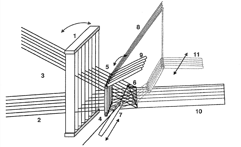
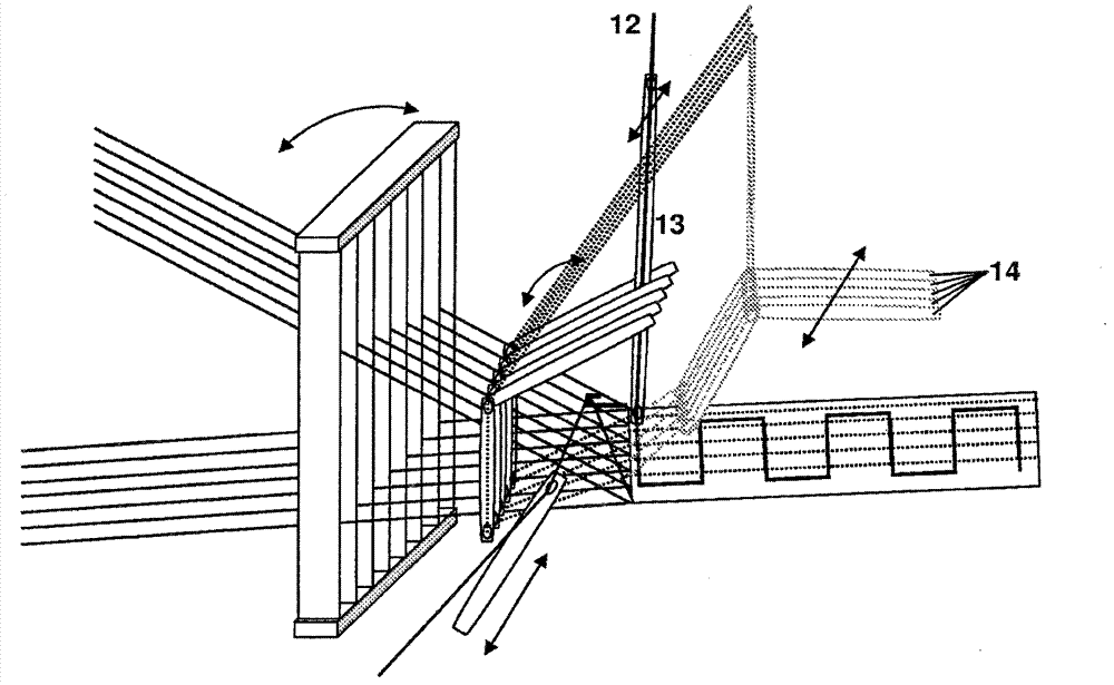
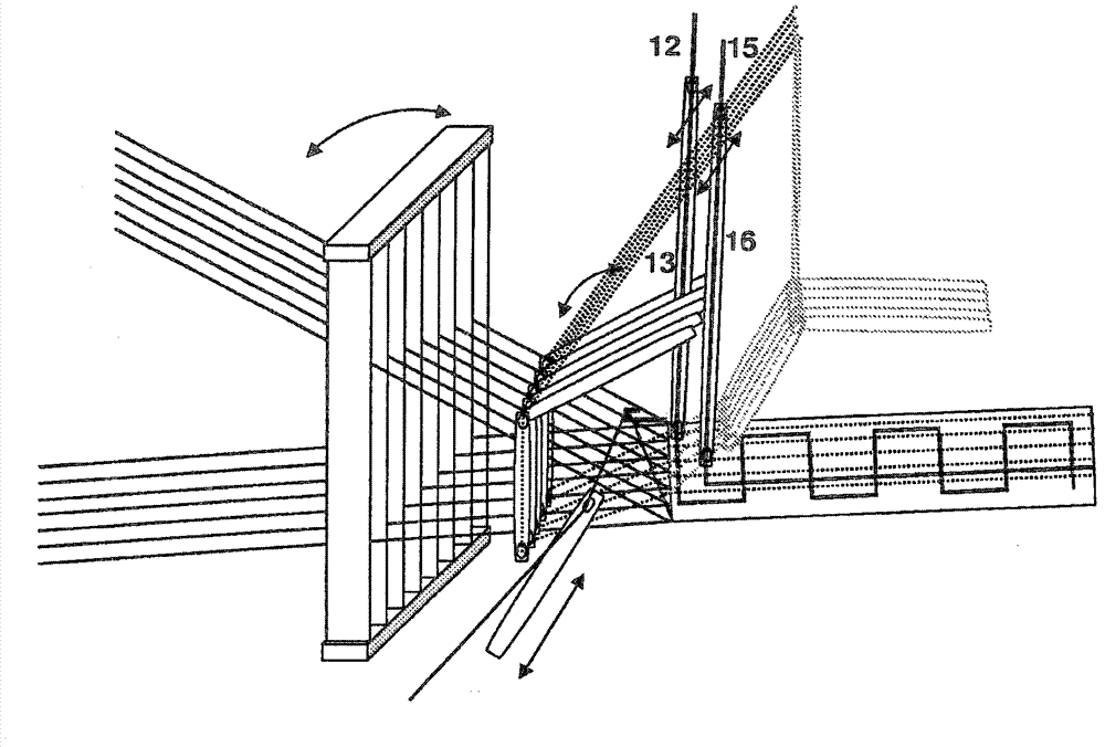
[0020] figure 1 is a schematic diagram of a loom of a first example of the invention showing the basic motions. In a projectile loom, the warp threads 2 used to manufacture the webbing 10 form an upper shed 5 and a lower shed 4 for the insertion of the weft threads by means of weft insertion needles 7 or projectiles. The reed 1 is arranged in a conventional manner on the previously manufactured braiding material 10 so as to be able to bear against the introduced weft threads.

[0021] The warp thread laying device 9 is inserted into the lower shed 4 through the upper shed 5 . Simultaneously, reed 1 moves backward. Warp yarn laying device 9 can move along the direction of steel reed 1, also can move down in the lower shed 4. In this embodiment, the warp laying device 9 moves with the movement of the reed 1 . However, the warp laying device can also be switched off or inserted at different frequencies depending on the bonding situation.

[0022] When the warp thread laying ...


PUM


Abstract

In order to improve a loom for producing woven goods or material (10) with an incorporated cover thread (12), it is proposed to provide a laying device at least one cover thread (12) and also a warp-laying device (9) with warp-laying elements (14) for laying further warp threads (8). The warp- laying device (9) is designed such that it can make the further warp threads (8) penetrate from a starting position through the upper shed (5) to the lower shed (4), or through the lower shed to the upper shed, and therefore the weft-insertion device (7) crosses the further warp threads (8). The laying device has at least one cover-thread guide (13) which, in the starting position of the warp-laying device (9), can be displaced transversely to the warp threads (2) by way of a transverse-movement means.

Description

technical field [0001] The present invention relates to a loom for the manufacture of woven material with incorporated cover threads. Background technique [0002] CH490541 has disclosed a loom of the above type. Among them, the connecting yarn is arranged by feeding needles while weaving the tape. However, no indication is given as to how the knitting braiding machine can weave conductive yarns, in particular antenna yarns, in a more advantageous manner. US3796234 also independently discloses a similar technique. [0003] A different way of inserting conductive yarns is known from WO 2007 / 071077 A1 by arranging feeding needles on an axis perpendicular to the warp direction, said axis being connected to a second A driving device is connected, and is further connected with a second driving device for producing axial deflection. Due to the pivoting movement, the blades are able to enter and leave the shed. Thus, the blades are able to move across the entire width of the b...

Claims


Application Information

Patent Timeline
Patent Type & Authority Applications(China)
IPC IPC(8): D03D31/00D03D35/00D03D41/00
CPCD03D41/00D03D31/00D03D35/00
Inventor W·斯达德S·比勒
Owner TEXTILMA AG
Learn More