Water-proof type self-heating floor

一种防水式、自发热的技术,应用在欧姆电阻防水/气密、加热方式、电热系统等方向,能够解决未解决地板系统防水问题、烧毁地板、制造复杂麻烦等问题

Active Publication Date: 2013-05-08
LINYI JIECHUANG CHEM IND PARK CO LTD
View PDF9 Cites 1 Cited by
  • Summary
  • Abstract
  • Description
  • Claims
  • Application Information

AI Technical Summary

Problems solved by technology

Among the above three installation methods, the "composite floor" in the third method covers a wide range. For example, laminate flooring is a kind of balanced paper layer, density board, decorative paper layer and wear-resistant paper from bottom to top Layers are formed by hot pressing, so structurally speaking, this kind of composite floor cannot pre-embed the heating wire, so those skilled in the art cannot implement the third installation method of the heating wire in this document.
As for the first two installation methods, there is a problem of making complicated troubles
[0008] Again, it is proposed in this document that the first connector, the second connector, the plug, the first joint and the second joint are all features of a waterproof structure, but it does not solve the waterproof problem of the entire floor system
Although the first joint and the second joint adopt a waterproof structure, there is no mention of how to solve the problem of waterproofing the connection between the two joints and the heating wire, nor does it involve the connection between the two joints and the floor board. The problem of sealing and waterproofing, when the floor system is not energized for a period of time, the water vapor in the air will enter the interior of the floor from the gap between the joint and the floor body, and condense at the joint between the joint and the heating wire. When the power is turned on, there will be serious leakage, which will cause the touch protector to trip immediately. If the touch protector is not installed, it will cause overheating or even burn the floor due to the generation of large current

Method used


Image

  • Water-proof type self-heating floor
  • Water-proof type self-heating floor
  • Water-proof type self-heating floor

Examples


Embodiment 1

[0161] (Example 1, waterproof self-heating floor)

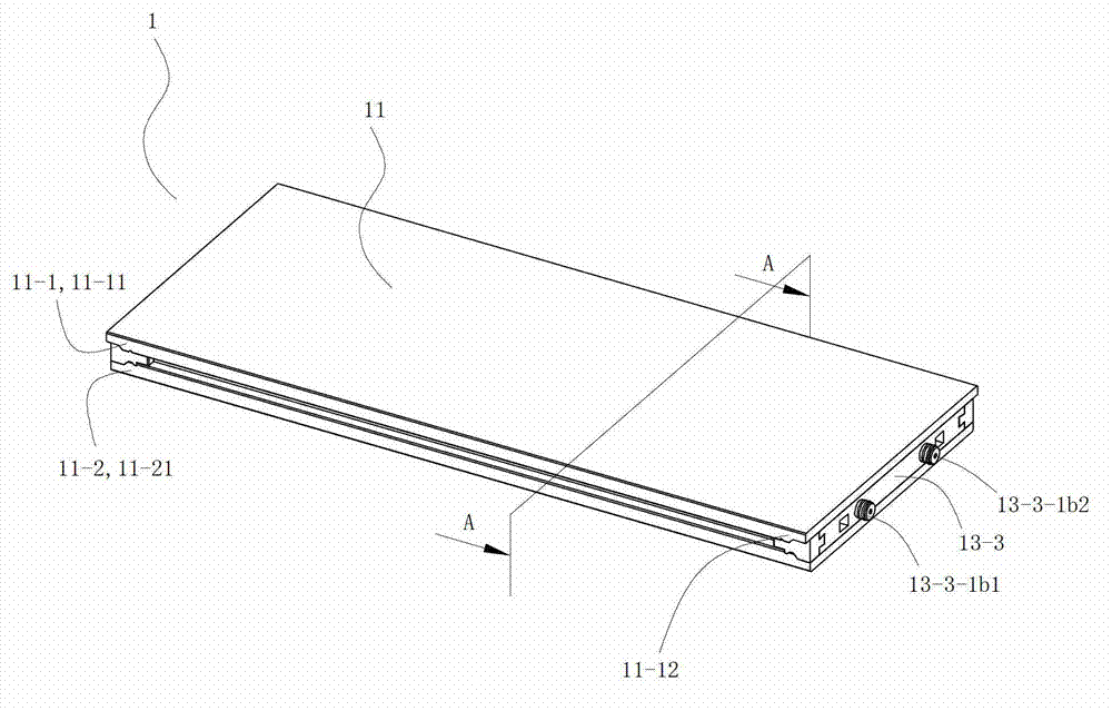
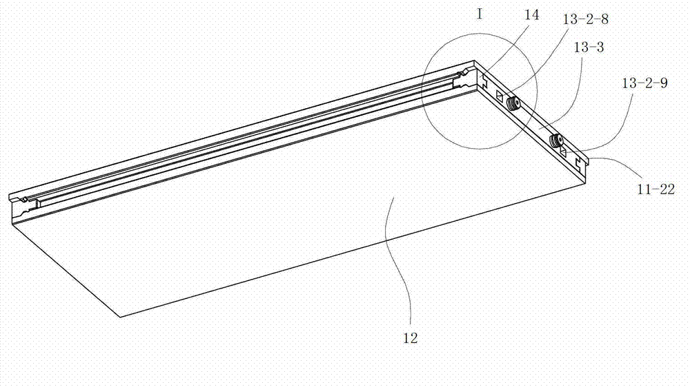
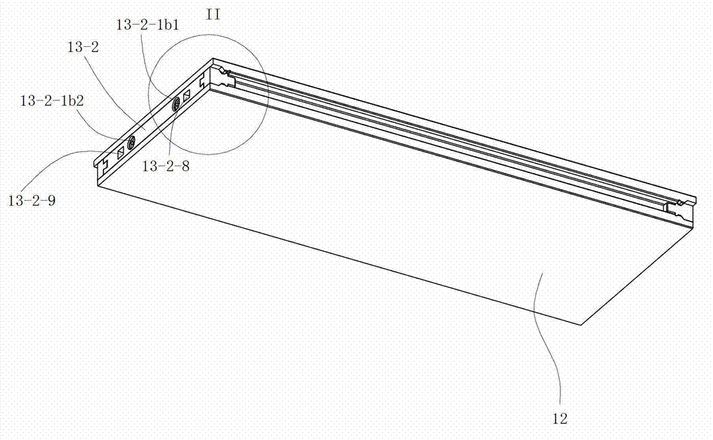
[0162] See Figure 1 to Figure 2 , Figure 14 and Figure 15 , The waterproof self-heating floor 1 of this embodiment includes an upper body 11 , a bottom plate 12 , a self-heating component 13 and a positioning block 14 .

[0163] See Figure 12 and Figure 13 The self-heating component 13 is a waterproof electric heating component, and the self-heating component 13 includes a transmission unit, a heating sheet 13-1, and socket parts 13-2 and double plug parts 13-3 respectively located at the left and right ends of the heating sheet 13-1. The transmission unit of the self-heating component 13 is composed of a waterproof live wire and a waterproof neutral wire, and the transmission unit of the self-heating component 13 includes two wires 13-4. The socket part 13-2 is a part that can be plugged and fixedly electrically connected with the double plug part 13-3 of the self-heating component 13 of the corresponding adjacent ...

Embodiment 2

[0196] (Example 2, waterproof self-heating floor)

[0197] The rest of the waterproof self-heating floor 1 of this embodiment is the same as that of Embodiment 1, the difference being that the length of the waterproof self-heating floor 2 of this embodiment is 1 / 2 of the length of the waterproof self-heating floor 1 of Embodiment 1. half.

Embodiment 3

[0198] (Example 3, waterproof self-heating floor)

[0199] The rest of the waterproof self-heating floor 1 of this embodiment is the same as that of Embodiment 1, and the difference is that no corresponding wire slot 12-4 is provided on the bottom plate 12.

[0200] See Figure 26 to Figure 28 , the rest of the self-heating assembly 13 of the present embodiment is the same as the self-heating assembly 13 of Embodiment 1, and its difference is that: the waterproof live wire and the waterproof zero wire of the transmission unit of the self-heating assembly 13 all include 2 conductive wires. Copper skin 13-6, aluminum foil 13-5 and polyvinyl chloride sheet 13-8. Each conductive copper skin 13-6 is fixed on the lower surface of the electric heater 13-1 from below, and the lower surface of each conductive copper skin 13-6 is coated with conductive glue. The shape of the aluminum foil 13-5 is the same as that of the strip-shaped conductive heating layer 13-1-1 of the electric heatin...


PUM


Abstract

The invention discloses a water-proof type self-heating floor which comprises a floor main body and a self-heating component. The floor main body comprises an upper portion main body and a base plate. The floor main body is adhered to the upper end face of the base plate by the lower end face of the upper portion main body. An inner portion cavity body is arranged between the upper portion main body and the base plate. The water-proof type self-heating floor is characterized in that power supply inserting pieces belonging to the self-heating component are arranged on the left side and the right side of the floor body, the self-heating component is a water-proof type electric heating component, an electric heating sheet of the self-heating component is arranged in an inner portion cavity body between a lower portion main body and an upper portion panel, a socket part is a water-proof connecting piece which is capable of being mutually connected with a corresponding and adjacent double-socket part of the self-heating component of the water-proof type self-heating floor in a plugged mode, and is fixedly and electrically connected with and mutually sealed with the corresponding and adjacent double-socket part of the self-heating component of the water-proof type self-heating floor when used, and the double-plug part is a water-proof connecting piece which can be mutually connected with the corresponding and adjacent socket part of the self-heating component of the water-proof type self-heating floor in a plugged mode, and can be fixedly and electrically connected with and mutually sealed with the corresponding and adjacent socket part of the self-heating component of the water-proof type self-heating floor.

Description

[0001] This application is a divisional application of the invention patent application with the application number 201110232044.3, the application date is August 15, 2011, and the invention name is "waterproof self-heating floor system and waterproof self-heating floor and its self-heating components". technical field [0002] The invention relates to a product in the field of building decoration, in particular to a waterproof self-heating floor. Background technique [0003] At present, the form of self-heating floor is electric heating floor. Electric heating floor has become a new heating method. It is to lay electric heating material in the floor and heat the floor by heating the electric heating material. [0004] Chinese patent document CN1034826C (application number 92114554.3) discloses an electric heating floor. The floor is provided with two through holes in the horizontal direction in the floor board, and the electric heating wire is inserted into the through hole...

Claims


Application Information

Patent Timeline
Patent Type & Authority Applications(China)
IPC IPC(8): H05B3/28H05B3/04F24D13/02E04F15/02
Inventor 葛林葛鑫琰
Owner LINYI JIECHUANG CHEM IND PARK CO LTD
Why Eureka
Try Eureka