Spontaneous heating assembly

A technology of self-heating components and electrical connection components, applied in ohmic resistance heating parts, heating methods, electrical components, etc., can solve problems that cannot be implemented, do not involve sealing and waterproofing, and burn the floor

Active Publication Date: 2013-05-01
泰州市海通资产管理有限公司
View PDF9 Cites 1 Cited by
  • Summary
  • Abstract
  • Description
  • Claims
  • Application Information

AI Technical Summary

Problems solved by technology

Among the above three installation methods, the "composite floor" in the third method covers a wide range. For example, laminate flooring is a kind of balanced paper layer, density board, decorative paper layer and wear-resistant paper from bottom to top Layers are formed by hot pressing, so structurally speaking, this kind of composite floor cannot pre-embed the heating wire, so those skilled in the art cannot implement the third installation method of the heating wire in this document.
As for the first two installation methods, there is a problem of making complicated troubles
[0008] Again, it is proposed in this document that the first connector, the second connector, the plug, the first joint and the second joint are all features of a waterproof structure, but it does not solve the waterproof problem of the entire floor system
Although the first joint and the second joint adopt a waterproof structure, there is no mention of how to solve the problem of waterproofing the connection between the two joints and the heating wire, nor does it involve the connection between the two joints and the floor board. The problem of sealing and waterproofing, when the floor system is not energized for a period of time, the water vapor in the air will enter the interior of the floor from the gap between the joint and the floor body, and condense at the joint between the joint and the heating wire. When the power is turned on, there will be serious leakage, which will cause the touch protector to trip immediately. If the touch protector is not installed, it will cause overheating or even burn the floor due to the generation of large current

Method used


Image

  • Spontaneous heating assembly
  • Spontaneous heating assembly
  • Spontaneous heating assembly

Examples


Embodiment 1

[0127] (Example 1, self-heating component)

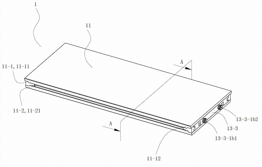
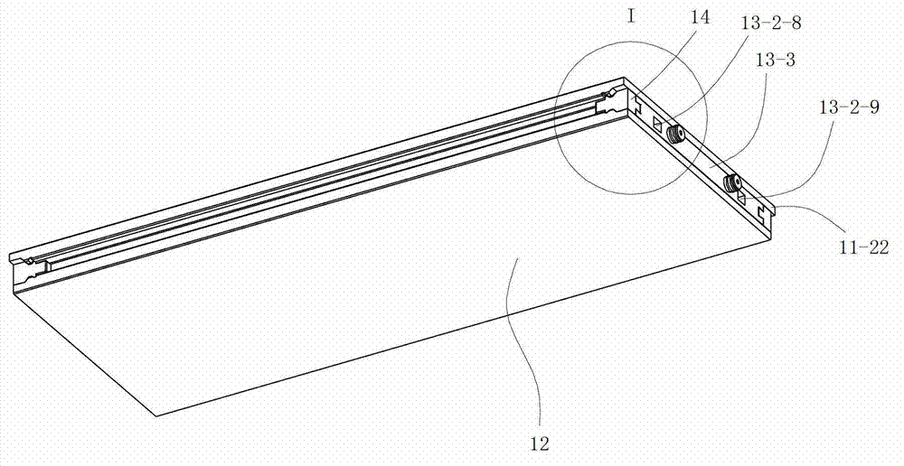
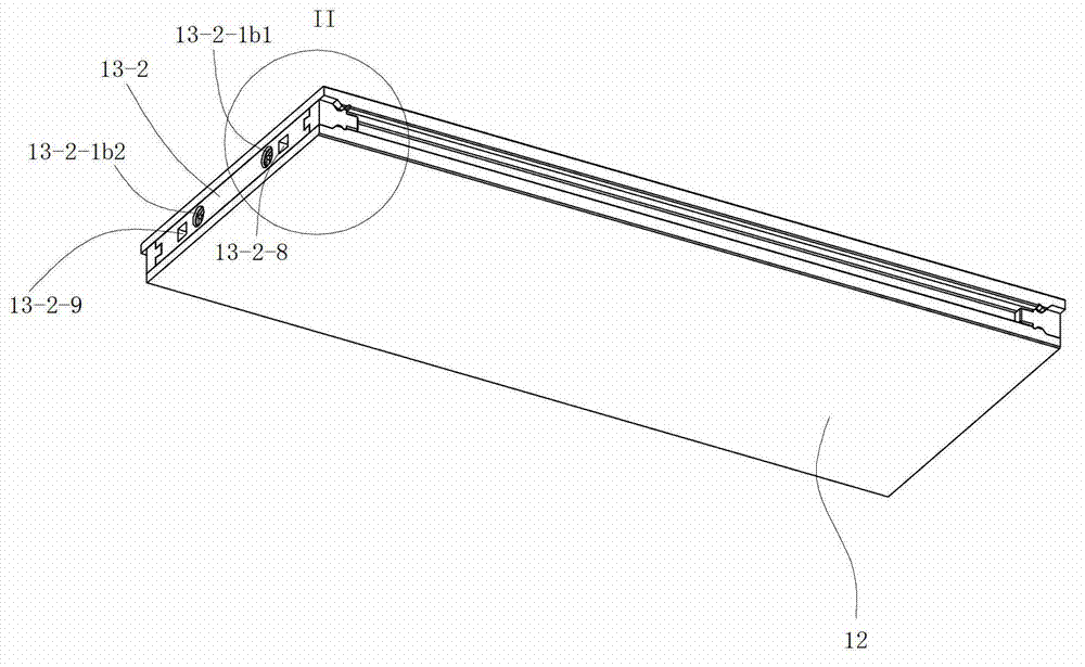
[0128] See Figure 12 with Figure 13 The self-heating component 13 is a waterproof electric heating component, and the self-heating component 13 includes a transmission unit, a heating sheet 13-1, and socket parts 13-2 and double plug parts 13-3 respectively located at the left and right ends of the heating sheet 13-1. The transmission unit of the self-heating component 13 is composed of a waterproof live wire and a waterproof neutral wire, and the transmission unit of the self-heating component 13 includes two wires 13-4. The socket part 13-2 is a part that can be plugged and fixedly electrically connected with the double plug part 13-3 of the self-heating component 13 of the corresponding adjacent waterproof self-heating floor 1 during use, and is connected with each other in a sealed and waterproof connection; the double plug The part 13-3 is a part that can be plugged and fixedly connected with the double plug part 13-3 of th...

Embodiment 2

[0148] (Example 2, self-heating components)

[0149] See Figure 13 The rest of the self-heating assembly 13 of this embodiment is the same as that of Embodiment 1, except that the conductive copper sheet 13-2-2 at the live wire end is located at the left connecting section 13-1a of the front heating sheet 13-11 The front end of the front is electrically connected with the first copper member 13-2-3c, and the first copper member 13-2-3c is electrically connected with the tail of the fire wire copper pin 13-2-3a, and the first copper member 13-2 -3c is electrically connected to the left end of the first electric wire 13-41 of the transmission unit by welding; the corresponding part involved in the above structure constitutes the first electrical connection component 13a1 on the socket side.

[0150] The tail end on the right side of the neutral line copper pin 13-2-3b is electrically connected to the second copper member 13-2-3d, and the second copper member 13-2-3d is then we...

Embodiment 3

[0153] (Example 3, self-heating components)

[0154] See Figure 26 to Figure 28, the rest of the self-heating assembly 13 of the present embodiment is the same as that of Embodiment 1, the difference is that: the waterproof live wire and the waterproof zero wire of the transmission unit of the self-heating assembly 13 all include two conductive copper sheets 13-6 , aluminum foil 13-5 and polyvinyl chloride sheet 13-8. Each conductive copper skin 13-6 is fixed on the lower surface of the electric heater 13-1 from below, and the lower surface of each conductive copper skin 13-6 is coated with conductive glue. The shape of the aluminum foil 13-5 is the same as that of the strip-shaped conductive heating layer 13-1-1 of the electric heating sheet 13-1, and is located below the electric heating sheet 13-1, and covers the strip-shaped conductive heating layer 13-1-1 from below. 1, and the upper surfaces of the left and right ends of the aluminum foil 13-5 are electrically connect...


PUM


Abstract

The invention discloses a spontaneous heating assembly. The spontaneous heating assembly is structurally characterized in that the spontaneous heating assembly is a waterproof type electric heating assembly and comprises electric heating sheets, a socket part located at one end of left and right ends of each electric heating sheet and a double-plug part located at the other end of the left and right ends of each electric heating sheet. One to five electric heating sheets are arranged and all the electric heating sheets are arranged on the same plane in parallel. A thin-sheet-shaped sealing waterproof type electric heating device of an electrode is respectively arranged at each one of the left and right ends of each electric heating sheet. The electric heating sheets are mutually connected in parallel or in series. The socket part is a waterproof connection part which can be mutually plugged, fixedly and electrically connected and mutually sealed with the double-plug part of the corresponding adjacent spontaneous heating assembly in a use process. The double-plug part is a waterproof connection part which can be mutually plugged, fixedly and electrically connected and mutually sealed with the socket part of the corresponding adjacent spontaneous heating assembly in the use process.

Description

[0001] This application is a divisional application of the invention patent application with the application number 201110232044.3, the application date is August 15, 2011, and the invention name is "waterproof self-heating floor system and waterproof self-heating floor and its self-heating components". technical field [0002] The invention relates to a product in the field of building decoration, in particular to a self-heating component used in a waterproof self-heating floor. Background technique [0003] At present, the form of self-heating floor is electric heating floor. Electric heating floor has become a new heating method. It is to lay electric heating material in the floor and heat the floor by heating the electric heating material. [0004] Chinese patent document CN1034826C (application number 92114554.3) discloses an electric heating floor. The floor is provided with two through holes in the horizontal direction in the floor board, and the electric heating wire ...

Claims


Application Information

Patent Timeline
Patent Type & Authority Applications(China)
IPC IPC(8): H05B3/28H05B3/04F24D13/02E04F15/02
Inventor 葛林葛鑫琰
Owner 泰州市海通资产管理有限公司
Why Eureka
Try Eureka