Waste heat utilization thermoelectric power generation pipeline device

A power generation device and thermoelectric power generation module technology, applied in the direction of generators/motors, electrical components, etc., can solve the problems of low technical level of low-temperature waste heat recovery, increase of cost capital, slow progress, etc., and achieve excellent heat flux variable performance and environmental protection The effect of improved adaptability and easy modification

Inactive Publication Date: 2013-05-08
CHONGQING UNIV
View PDF2 Cites 5 Cited by
  • Summary
  • Abstract
  • Description
  • Claims
  • Application Information

AI Technical Summary

Problems solved by technology

However, the promotion and application of domestic medium and high temperature waste heat recovery technology is insufficient, and the level of low temperature waste heat recovery technology is low, resulting in a very low overall efficiency of industrial waste heat recovery in my country.
[0005] In the existing heat pipe thermoelectric power generation technology, most of the research focuses on the improvement of the power generation efficiency of the thermoelectric power generation module, and the research investment is large and the progress is slow
However, little attention has been paid to the heat transfer process from the pipe to the hot end of the thermoelectric power generation module. The heat pipe or the thermoelectric power generation module is simply attached to the pipe surface or inserted into the pipe, which inevitably makes the layout of the components affected by the shape of the pipe or even increased. The fluid flow resistance in the pipeline increases the operating burden of the system, and makes the heat pipe and thermoelectric power generation module in a relatively harsh working environment, which cannot be in the best working condition, and the damage rate increases, which virtually increases the cost of funds

Method used


Image

  • Waste heat utilization thermoelectric power generation pipeline device
  • Waste heat utilization thermoelectric power generation pipeline device
  • Waste heat utilization thermoelectric power generation pipeline device

Examples


Embodiment Construction

[0013] The present invention will be further described in detail below with reference to the drawings and specific embodiments.

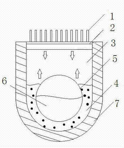
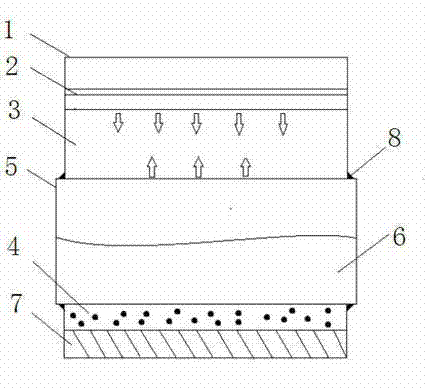
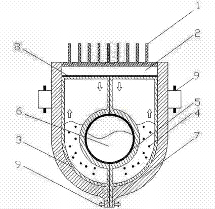
[0014] figure 1 , figure 2 It is a schematic diagram of the structure of the waste heat thermoelectric power generation tube, as shown in the figure: the medium and low temperature thermal fluid 6 with waste heat flows in the heat flow pipe 5, and the heat flow pipe 5 is covered by the working medium 4 of the heat transfer device. The U-shaped part of the heat transfer device 3 has good thermal insulation performance to reduce the heat loss during the phase change transfer process of the working fluid 4 of the heat transfer device. The horizontal part of the heat transfer device 3 closely connected to the hot end of the thermoelectric power generation module 2 has good thermal conductivity to ensure High efficiency utilization of working fluid heat. The cold end of the thermoelectric power generation module 2 is in close contact with the heat sink fin...


PUM


Abstract

The invention discloses a novel pipeline device aiming at transforming low-grate heat energy of living industry into electric energy. The pipeline device is mainly composed of five parts such as a heat flow pipeline, a heat transfer device, a thermoelectric power generation module, a cooling system and an electric power storage control module. Waste heat in the heat flow pipeline is transmitted to a hot end of the thermoelectric power generation module through working medium phase change in the heat pipe heat transfer device, and a cool end of the thermoelectric power generation module is continuously cooled by the cooling system, so that the two end of the power generation module is enabled to form temperature difference to generate power. The electric power storage control module is used for ensuring the continuity of energy transformation and stability of power output. For an existing pipeline, a pipeline clamping thermoelectric power generation device is designed additionally. Theories are basically the same, but a heat conduction glue layer is added between the existing pipeline and the heat pipe heat transfer device to reduce thermal resistance. The clamping device can be designed according to the existing pipeline size in a matching mode. The waste heat utilization thermoelectric power generation pipeline device aims at solving the problems that the thermoelectric power generation module is not influenced by limiting of the pipeline outside in an existing industrial waste heat recovery thermoelectric power generation technology and heat conduction efficiency is not high.

Description

Technical field [0001] The invention relates to a semiconductor thermoelectric power generation technology, in particular to a thermoelectric power generation technology based on the principle of heat pipes for the utilization of waste heat from pipes of any shape in matching horizontal and belongs to the field of industrial waste heat power generation. Background technique [0002] As the contradiction between energy supply and demand continues to deepen, the energy problem has become an urgent problem in the development of human society. While vigorously developing new energy, it is also a feasible way to improve the utilization efficiency of primary energy in the industrial sector. my country's energy utilization rate is only about 30%, which is about 10% lower than that of developed countries. At least 50% of industrial energy consumption is directly discarded as waste heat in various forms. If this part of the waste heat can be used, it can not only effectively improve the ...

Claims


Application Information

Patent Timeline
Patent Type & Authority Applications(China)
IPC IPC(8): H02N11/00
Inventor 崔文智周陇何杰焦玉龙
Owner CHONGQING UNIV
Why Eureka
Try Eureka