
Laser module temperature control testing device

A test device and laser module technology, applied in the field of laser applications, can solve problems affecting test accuracy, temperature change speed and temperature control range, vibration and static electricity, etc., to achieve the effect of improving test efficiency, good test environment, and simple operation

Active Publication Date: 2013-05-08
QINGDAO LASENCE
View PDF6 Cites 1 Cited by
  • Summary
  • Abstract
  • Description
  • Claims
  • Application Information

AI Technical Summary

Problems solved by technology

This test method has many defects: first, this test method introduces many variables, and the platform, radiator, cooling plate, and V-shaped groove will cause great deviations in the accuracy of the test results due to thermal expansion and contraction; especially laser point drift Second, due to the lack of heat insulation structure, the heat capacity of the heat dissipation end is large, which seriously affects the temperature change speed and temperature control range; third, the fixing method generally uses screws to directly hold it, and the contact part between the screw and the product is irregular, which will cause the product to be clamped. And unstable; Fourth, radiators generally use fans to dissipate heat or water circulation to dissipate heat, which will generate vibration and static electricity, which will affect the test accuracy and cause product damage

Method used


Image

  • Laser module temperature control testing device
  • Laser module temperature control testing device
  • Laser module temperature control testing device

Examples


Embodiment 1

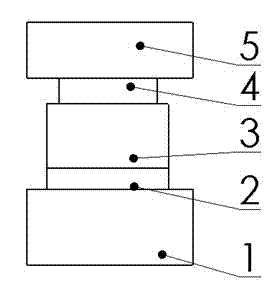
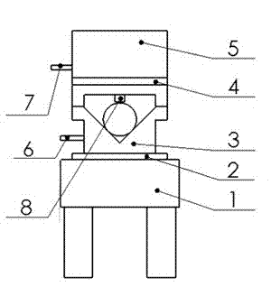
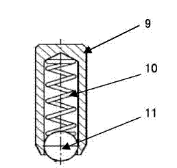
[0028] The laser module temperature control test device of the present invention comprises a fixed platform 1, and a clamping device 3, a cooling plate 4, and a radiator 5 are arranged from bottom to top above the fixed platform 1, and it also includes a temperature control device, which includes a single-chip microcomputer, a temperature control device, and a temperature control device. Sensors and temperature sensors are connected to the single-chip microcomputer, and are centrally controlled by the single-chip microcomputer. The temperature sensor is fixed on the radiator and the clamping device, and the first temperature sensor 6 is connected to the clamping device, and the second temperature sensor 7 is connected to the radiator. , the single chip microcomputer automatically adjusts the PID parameter value according to the feedback temperature difference of the temperature sensor. A thermal insulation board 2 is arranged between the clamping device 3 and the fixed platform...

Embodiment 2

[0031] The difference between this embodiment and Embodiment 1 is that the heat insulation plate of this embodiment is made of alumina, and the material of the clamping device and the heat sink is made of steel.

Embodiment 3

[0033] The difference between this embodiment and Embodiment 1 is that the heat insulating plate of this embodiment is set as ceramics, and the material of the clamping device and the heat sink is set as copper.


PUM


Abstract

The invention relates to the field of laser application, and particularly provides a laser module temperature control testing device with high accuracy. The testing device is capable of providing a wider temperature control range and improves temperature changing speed and testing efficiency by a clamping device being changed, heat dissipation parts being changed to reduce an influence of expansion with heat and contraction with cold on tests, a heat insulation piece being increased and heat dissipation structures being changed. The laser module temperature control testing device comprises a fixed platform. A clamping device, a refrigeration piece and a radiator are arranged above the fixed platform from bottom to up. The laser module temperature control testing device further comprises a temperature control device. The temperature control device comprises a single chip computer and temperature sensors. The temperature sensors are connected with the single chip computer and are controlled by the single chip computer concentratedly. The temperature sensors are fixed on the radiator and the clamping device, the single chip computer adjusts proportional integral derivative (PID) parameter values automatically according to feedback temperature differences of the temperature sensors. In testing, products just need to be inserted to be positioned well, and therefore the laser module temperature control testing device is easy to operate, is good in consistency, and improves testing efficiency largely.

Description

[0001] technical field [0002] The invention relates to the field of laser applications, in particular to a high-precision laser module temperature control testing device. [0003] Background technique [0004] With the continuous development of science and technology, the application of laser products is also increasing, and the demand for small, light, and reliable indicating laser modules is increasing. Some high-tech, high-precision instruments and equipment require laser The requirements for module stability are also constantly increasing, which makes the laser module have very high requirements for test accuracy and precision, and the measurement error introduced by the test must be very small. [0005] At present, the usual module testing method is: put the temperature control structure with V-shaped groove on a platform, and clamp the module on the V-shaped groove for testing. This test method has many defects: first, this test method introduces many variables, an...

Claims


Application Information

Patent Timeline
IPC IPC(8): G05D23/20G05B19/042
Inventor 马世建邱港刘瑞霞陆之成
Owner QINGDAO LASENCE
Learn More