
A gas temperature control device

A technology for controlling device and gas temperature, which is applied in the field of lithography machines, and can solve problems such as inability to achieve high-precision temperature control and general temperature control accuracy

Active Publication Date: 2016-02-03
SHANGHAI MICRO ELECTRONICS EQUIP (GRP) CO LTD
View PDF7 Cites 0 Cited by
  • Summary
  • Abstract
  • Description
  • Claims
  • Application Information

AI Technical Summary

Problems solved by technology

However, there is only one temperature control circuit for this device. In addition, since there is no power system in the cooling circuit, there will be no internal circulation, resulting in a general temperature control accuracy. Achieve high-precision temperature control

Method used

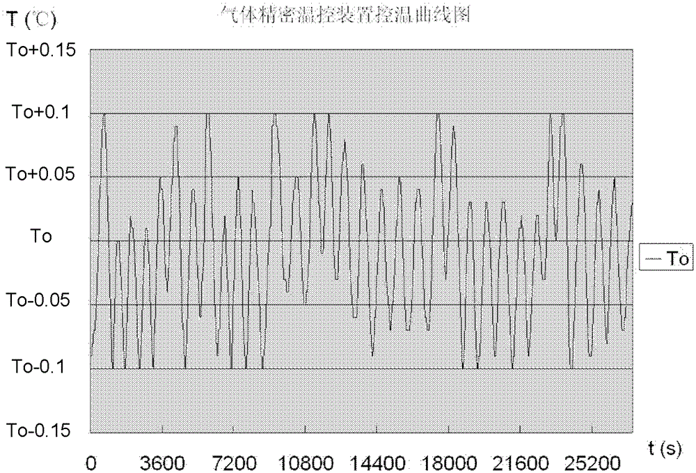

Image

  • A gas temperature control device
  • A gas temperature control device
  • A gas temperature control device

Examples


Embodiment Construction

[0028] In order to better understand the technical content of the present invention, specific embodiments are given together with the attached drawings for description as follows.

[0029] There are many heat sources inside the lithography machine, which affect the overall internal environment and have a great impact on its exposure performance. In order to ensure the temperature stability and uniformity of local key areas, a gas temperature control device for lithography machines is invented. Through this device, the temperature-controlled air is sent into the interior of the lithography machine, and a partial air bath is performed on the above-mentioned area, focusing on maintaining the environment of the key areas inside the machine and improving the exposure accuracy of the lithography machine.

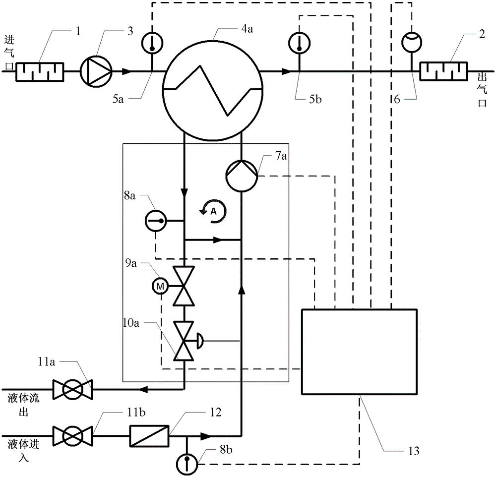
[0030] Please refer to figure 2 , figure 2 Shown is a schematic structural diagram of the gas temperature control device of the first preferred embodiment of the present invent...


PUM


Abstract

The invention provides a gas precise temperature control device, comprising a gas side pipeline, a liquid side circuit and a controller. The liquid side circuit comprises a first circuit and a second circuit, and is connected to a heat exchanger; the second circuit comprises an electric two-way valve, a manual voltage regulation valve, a circulating pump and a temperature sensor; and the first circuit comprises a ball valve, a filter and a temperature sensor. he gas precise temperature control device provided by the invention adopts a two-stage liquid circulating temperature control system, and has no accuracy requirements on the circulating liquid for cooling or heating; flow of the liquid entering in the circuit is controlled to conduct heat and cold compensation, and to obtain high gas temperature control accuracy, so as to ensure the stability and homogeneity indexes of the temperature in the lithography machine.

Description

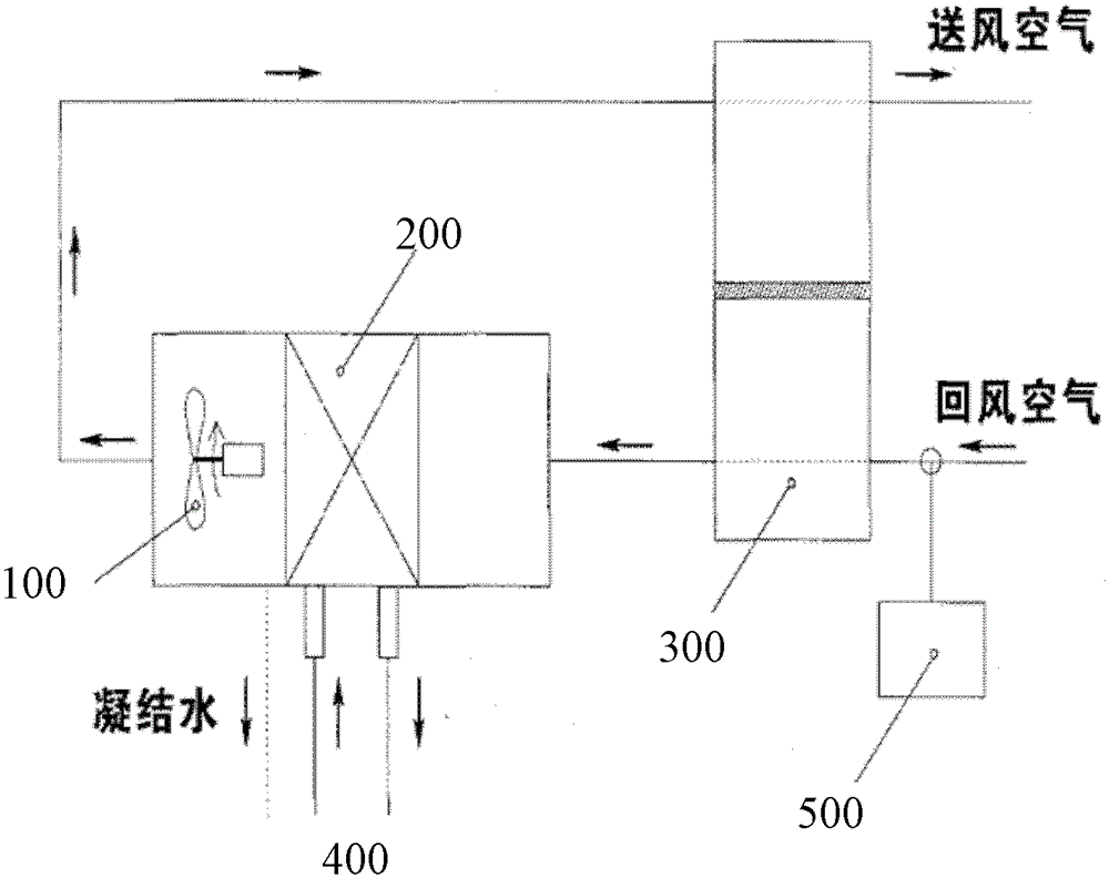
technical field [0001] The invention relates to the field of photolithography machines, and in particular to a gas temperature control device. Background technique [0002] At present, when the equipment in the semiconductor, medical equipment and other industries is running, the accuracy of the ambient temperature is getting higher and higher. Therefore, the design of high-precision temperature control devices has become an important issue in related industries. [0003] The prior art discloses an air conditioner for supplying air to intelligent buildings, which consists of an indoor unit and an outdoor unit. The indoor unit includes: fan 100, surface cooler 200 (air cooling heat exchanger), sensible heat ventilation core 300, refrigerant 400, temperature and humidity control mechanism 500, the indoor unit can be used alone in the centralized air conditioning system, the schematic diagram of the temperature control device is shown in figure 1 . [0004] In the surface coo...

Claims


Application Information

Patent Timeline
IPC IPC(8): G03F7/20
Inventor 王明张洪博聂宏飞杨志斌王飞
Owner SHANGHAI MICRO ELECTRONICS EQUIP (GRP) CO LTD
Learn More