Fan coil unit assembly and filter device for fan coil air inlet

A technology for a fan coil unit and a filter device is applied to the fan coil unit assembly and the filter device field of the fan coil unit air inlet. Disassembly and assembly, saving labor costs, and simplifying the effect of disassembly and assembly work

Active Publication Date: 2016-03-23
CSMC TECH FAB2 CO LTD
View PDF4 Cites 2 Cited by
  • Summary
  • Abstract
  • Description
  • Claims
  • Application Information

AI Technical Summary

Problems solved by technology

Due to the narrow space in the ceiling, the process of disassembling and assembling the filter is extremely inconvenient, consumes a lot of labor costs, and poses safety hazards

Method used


Image

  • Fan coil unit assembly and filter device for fan coil air inlet
  • Fan coil unit assembly and filter device for fan coil air inlet
  • Fan coil unit assembly and filter device for fan coil air inlet

Examples


Embodiment Construction

[0030] In the following description, numerous specific details are given in order to provide a more thorough understanding of the present invention. It will be apparent, however, to one skilled in the art that the present invention may be practiced without one or more of these details. In other examples, some technical features known in the art are not described in order to avoid confusion with the present invention.

[0031] In order to provide a thorough understanding of the present invention, the detailed structure will be set forth in the following description. It is evident that the practice of the invention is not limited to specific details familiar to those skilled in the art. Preferred embodiments of the present invention are described in detail below, however, the present invention may have other embodiments besides these detailed descriptions.

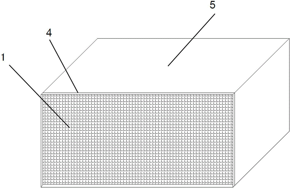
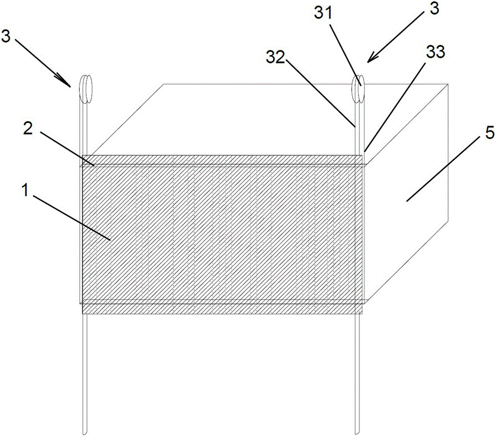
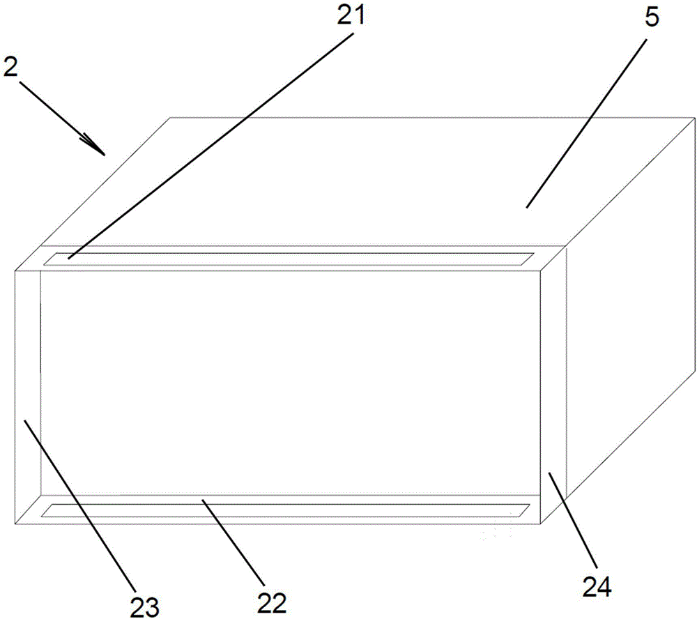
[0032] like figure 2 As shown, the filter device for the air inlet of a fan coil unit according to the first embodimen...


PUM


Abstract

The invention discloses a fan coil component and a filter device of a fan coil air inlet. The filter device comprises a filter, a guide device and a drive device. The guide device is fixed at the end of the fan coil air inlet and used for guiding the filter to move up and down. The drive device is connected with the filter and used for driving the filter to move along the guide device. By the filter device, safe and convenient mounting and demounting of the filter device are achieved.

Description

technical field [0001] The invention relates to the technical field of air conditioning, in particular to a fan coil assembly and a filter device for an air inlet of the fan coil. Background technique [0002] Fan coil unit is an ideal terminal product of central air-conditioning, widely used in hotels, office buildings, hospitals, commercial and residential, and scientific research institutions. The fan coil unit is composed of fan, motor, coil, filter, room temperature adjustment device and box. Among them, the fan circulates the indoor air, so that the air passes through the coil for cold water or hot water, and is cooled or heated to maintain the room temperature and meet people's comfort requirements. Among them, the function of the filter is to filter the dust in the indoor circulating air, improve the hygienic conditions of the room, and at the same time protect the coil from being blocked by dust, so as to ensure the air volume and heat exchange effect. [0003] Mo...

Claims


Application Information

Patent Timeline
Patent Type & Authority Patents(China)
IPC IPC(8): F24F13/28F24F1/00
Inventor 于凯歌
Owner CSMC TECH FAB2 CO LTD
Why Eureka
Try Eureka