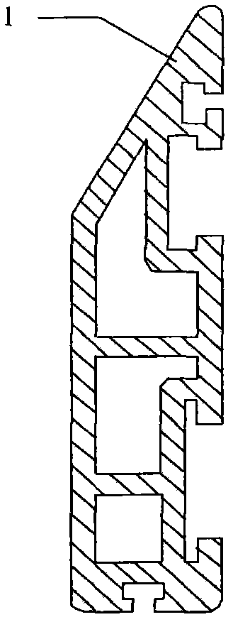
Bottom sealing device for industrial equipment
A technology for sealing devices and industrial equipment, applied in mechanical equipment, engine sealing, tobacco, etc., can solve problems such as poor tolerance of magnets and slots, high processing and manufacturing costs, and affecting the installation effect of sealing plates, etc., to achieve assembly and disassembly Convenience, reduce manufacturing cost, and prevent foreign matter from entering the bottom of the equipment
- Summary
- Abstract
- Description
- Claims
- Application Information
AI Technical Summary
Problems solved by technology
Method used
Image

Examples
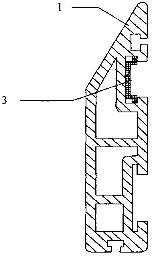
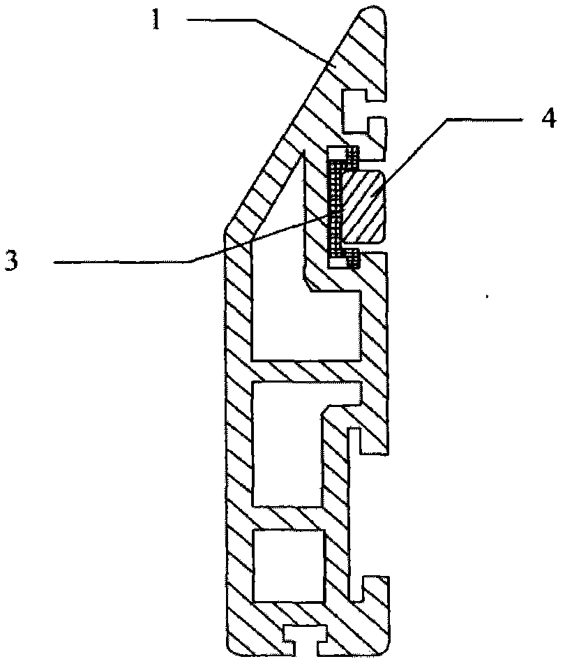
Embodiment 1
[0024] see image 3 The sealing device at the bottom of the industrial equipment shown includes a sealing plate 1, an elastic slider 3, and a magnet 4. The elastic slider 3 is directly inserted into the slot of the sealing plate 1, and the magnet 4 is connected and fixed through the elastic slider 3. The elastic slider 3 and The connecting body of the magnet 4 can freely displace in the card slot, and can be clamped at any position in the card slot.
Embodiment 2
[0026] see Figure 4 The sealing device at the bottom of the industrial equipment shown includes a sealing plate 1, a sealing strip 2, an elastic slider 3, and a magnet 4. The elastic slider 3 is directly inserted into the slot of the sealing plate 1, and the magnet 4 is connected and fixed by the elastic slider 3. The connecting body of the slider 3 and the magnet 4 can freely displace in the slot, and can be clamped at any position in the slot.
[0027] The sealing strip 2 can be in one or more strips, for example, two sealing strips 2 .
Embodiment 3
[0029] see Figure 5 The schematic diagram of the whole set of equipment and the installation position of the equipment, in which the sealing device at the bottom of the industrial equipment includes a sealing plate 1, a sealing strip 2, an elastic slider 3, and a magnet 4. The elastic slider 3 is directly inserted into the slot of the sealing plate 1, and the magnet 4 The elastic slider 3 is connected and fixed, and the connecting body of the elastic slider 3 and the magnet 4 can freely displace in the slot, and can be clamped at any position in the slot. Fix the sealing device at the bottom of the industrial equipment with the side 5 of the bottom of the equipment through the magnet 4 and make it close to the ground 6 . During on-site installation, the position of the connecting body of the magnet 4 and the elastic slider 3 in the slot of the sealing plate 1 can be adjusted freely according to the specific conditions on the site, and clamped tightly. The gap 7 existing at t...
PUM
 Abstract
Description
Claims
Application Information
 - R&D
- Intellectual Property
- Life Sciences
- Materials
- Tech Scout
- Unparalleled Data Quality
- Higher Quality Content
- 60% Fewer Hallucinations
Browse by: Latest US Patents, China's latest patents, Technical Efficacy Thesaurus, Application Domain, Technology Topic, Popular Technical Reports.
© 2025 PatSnap. All rights reserved.Legal|Privacy policy|Modern Slavery Act Transparency Statement|Sitemap|About US| Contact US: help@patsnap.com