
Internal gear pump

一种齿轮式、齿顶的技术,应用在旋转活塞式泵、泵、旋转活塞式机械等方向,能够解决无法提高容积效率、无法减小运送侧顶端间隙等问题,达到静音性良好、抑制泄露、提高泵效率的效果

Active Publication Date: 2013-05-08
YAMADA SEISAKUSHO KK
View PDF8 Cites 0 Cited by
  • Summary
  • Abstract
  • Description
  • Claims
  • Application Information

AI Technical Summary

Problems solved by technology

Therefore, the tip clearance on the delivery side cannot be reduced, the leakage is not reduced, and the volumetric efficiency cannot be improved

Method used


Image

  • Internal gear pump
  • Internal gear pump
  • Internal gear pump

Examples


Embodiment Construction

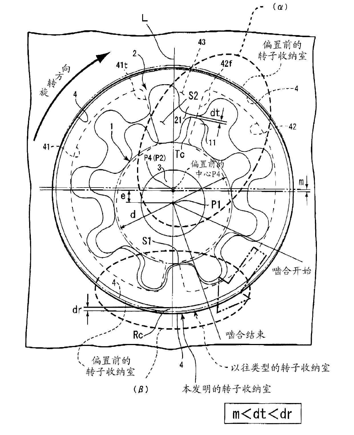
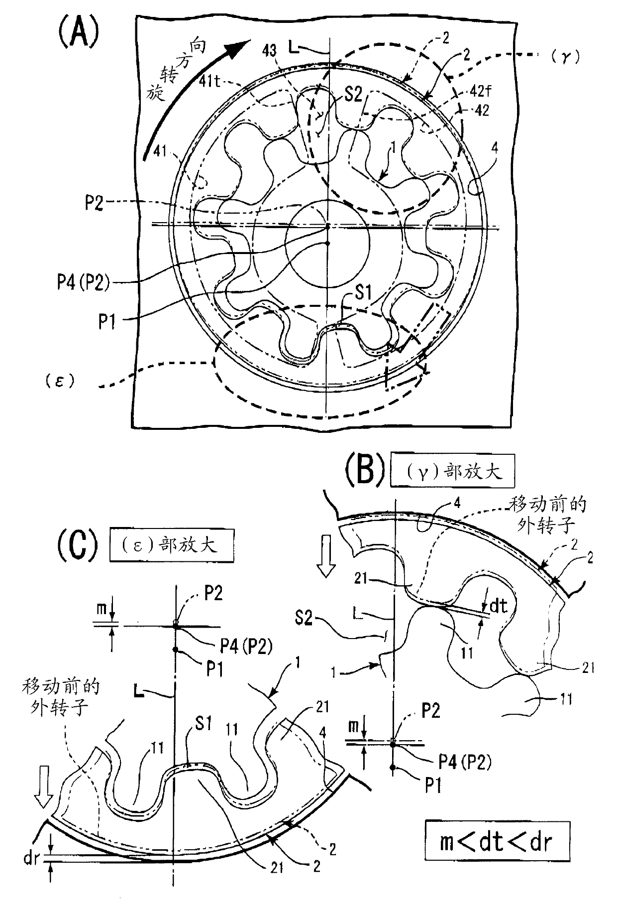
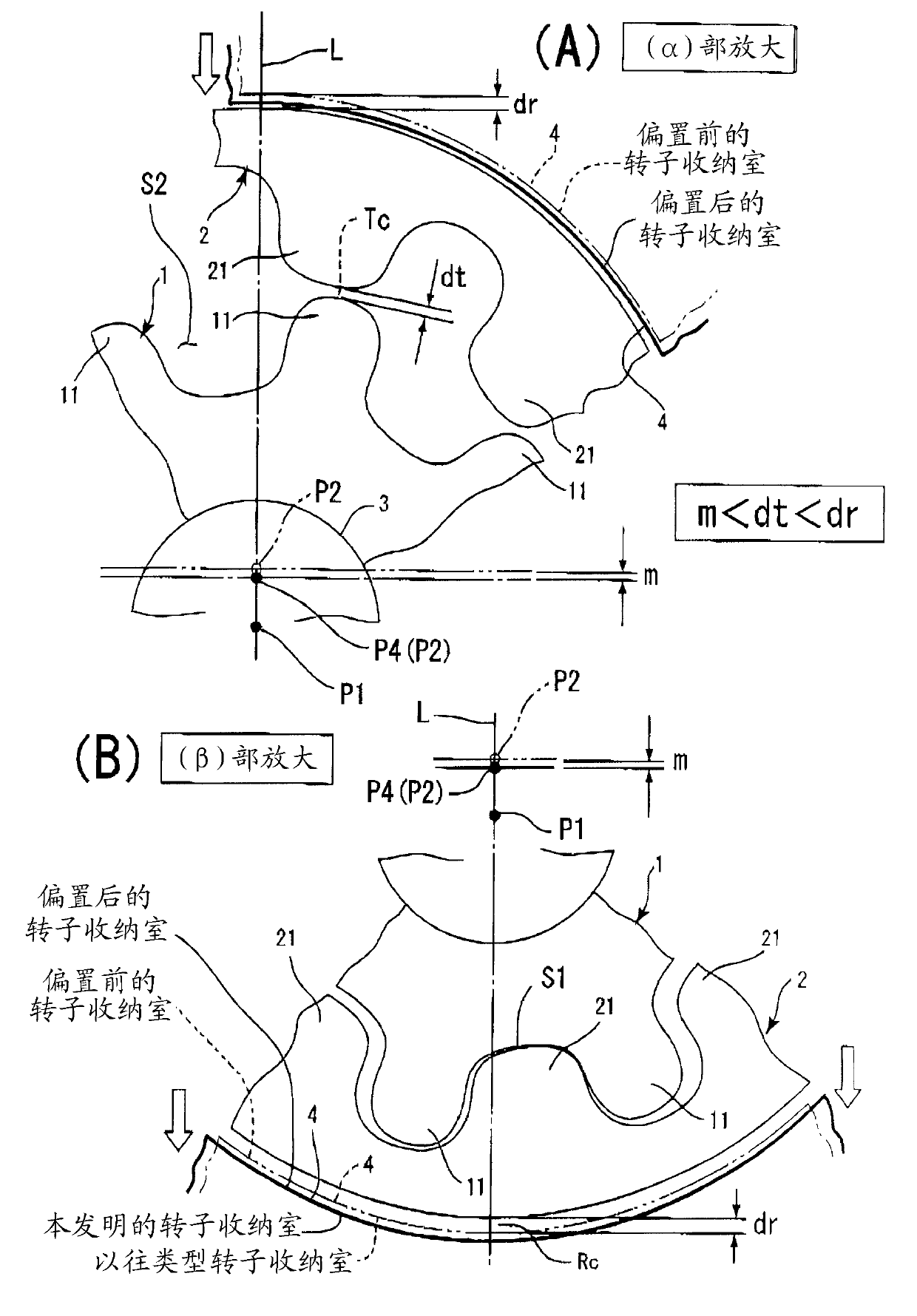
[0028] Hereinafter, embodiments of the present invention will be described based on the drawings. In the present invention, the pump rotor constitutes the rotor of the internally connected gear pump, specifically, the inner rotor 1 and the outer rotor 2 (refer to figure 1 ). The inner rotor 1 is a gear with external teeth, and the outer rotor 2 is a gear with internal teeth. exist figure 1 In , the arrows of the two-dot chain line described in the range from the meshing start to the meshing end indicate the force applied from the inner rotor 1 to the outer rotor 2 .

[0029] Furthermore, the pump rotor is not a trochoidal tooth shape, but a so-called high-volume tooth shape that realizes an increase in the theoretical discharge amount. The high-volume tooth profile, for example, the tooth profile 11 of the inner rotor 1 is formed by combining a plurality of ellipses and circles, or curves of higher order.

[0030] In the present invention, in the pump rotor, let the rotati...


PUM


Abstract

A pump rotor is an inner rotor of an internal gear pump, the inner rotor having a tooth profile (A), wherein a half-tooth portion (A1) of the tooth profile (A) is formed of three tooth-profile formation circles (C) that are elliptical or true-circular. Two of the tooth-profile formation circles (C) are a combination of a small tooth-profile formation circle and a large tooth-profile formation circle in which the small tooth-profile formation circle is inscribed and is entirely included. A portion of the small tooth-profile formation circle forms an addendum portion (1) of the half-tooth portion (A1). A portion of the large tooth-profile formation circle in which the small tooth-profile formation circle is inscribed and is entirely included forms an engagement portion (2) of the half-tooth portion (A1). A portion of another tooth-profile formation circle that circumscribes the large tooth-profile formation circle forms a dedendum portion (3) of the half-tooth portion (A1).

Description

technical field [0001] The invention relates to an internal gear pump capable of improving volumetric efficiency. Background technique [0002] Conventionally, there is an internal gear type pump composed of an inner rotor and an outer rotor. Furthermore, various researches and developments have been carried out on tooth profiles of the inner rotor and the outer rotor, and inventions for improving pump efficiency have been proposed. As such inventions, there are Patent Document 1, Patent Document 2, and the like. [0003] First, in Japanese Patent Application Laid-Open No. 55-148992, it is the deepest meshing portion where the teeth of the inner rotor start to press against (or start meshing with) the teeth of the outer rotor. As a result, a force is applied to the outer rotor from the deepest meshing portion toward the front side in the rotation direction of the rotor. That is, a substantially lateral force is applied to the outer rotor with respect to the delivery side ...

Claims


Application Information

Patent Timeline
Patent Type & Authority Applications(China)
IPC IPC(8): F04C2/10
CPCF04C2/102F04C2/084F01C1/00
Inventor 藤木谦一井筒正人
Owner YAMADA SEISAKUSHO KK
Learn More