Fuel supply system

A technology for a fuel supply system and a fuel supply device, which is applied in the directions of fuel injection control, combustion engine, internal combustion piston engine, etc., can solve the problems of difficulty in reducing current consumption, large valve lift, and inability to remove foreign matter, and achieves a reduction in the passage of electricity. Effectiveness of flow rate, failure avoidance, and current consumption reduction

Inactive Publication Date: 2013-05-08
MITSUBISHI ELECTRIC CORP
View PDF5 Cites 2 Cited by
  • Summary
  • Abstract
  • Description
  • Claims
  • Application Information

AI Technical Summary

Problems solved by technology

However, in this case, since the lift amount of the valve portion is maximized only periodically for a certain period of time, foreign matter may not be removed.
In addition, although it is possible to maintain the maximum lift of the valve part by duty cycle control, from the viewpoint of product miniaturization, there is a need to reduce the current consumption. In some cases, it is necessary to always energize the pressure regulator, so it is difficult to reduce the current consumption

Method used


Image

  • Fuel supply system
  • Fuel supply system
  • Fuel supply system

Examples


Embodiment approach 1

[0043] The fuel supply system according to Embodiment 1 of the present invention will be described. figure 1 It is a block diagram of the fuel supply system of Embodiment 1.

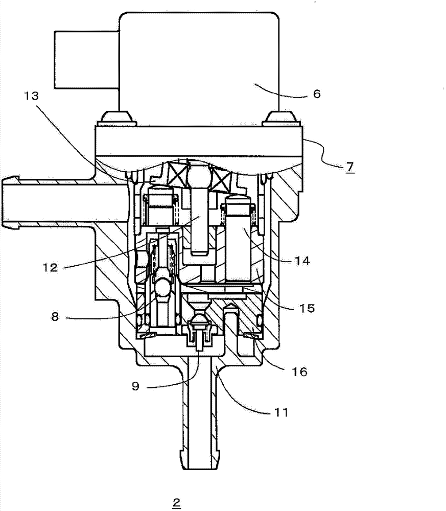
[0044] exist figure 1 Among them, the fuel supply system 10 includes: a fuel tank 1 for storing fuel; a fuel supply device 2; a fuel injection device 3 for discharging fuel to an air intake pipe (not shown); and a control unit (hereinafter referred to as ECU) 5 that controls the fuel supply device 2 and the fuel injection device 3 . The fuel supply device 2 includes: a brushless motor 6 ; a piston pump 7 as a pump device driven by the brushless motor 6 as described below; a pressure regulating device 8 ; and a fuel pressure maintaining valve 9 . In addition, the fuel piping between the fuel tank 1 and the fuel injection device 3 is configured such that fuel flows in a certain direction without backflow. In addition, in figure 1 In the illustrated case, the pressure regulating device 8 is built in the...


PUM


Abstract

A fuel supply system of an internal combustion engine is provided. The fuel supply system controls a discharge flow of the fuel supply system during control of non-injection and the minimum injection of a fuel injection apparatus, so as to control a passing flow of a pressure regulating device. The fuel supply system (10) comprises a fuel tank (1) for accommodating fuel; a fuel supply apparatus (2) driven by a brushless motor (6); a filtering device (4) arranged between the fuel tank (1) and the fuel supply apparatus (2); the pressure regulating device (8) arranged in the fuel supply apparatus (2) or adjacent to the fuel supply apparatus (2); the fuel injection apparatus (3) for injecting the fuel pressurized by the fuel supply apparatus (2); and a control unit for controlling on-off time points of the fuel injection apparatus (3) and motor rotational speed of the fuel supply apparatus (2), and controlling the flow passing the pressure regulating device (8) by controlling the discharge flow of the fuel supply apparatus (2).

Description

technical field [0001] The present invention relates to a fuel supply system for controlling the fuel pressure to a target value by using a pressure regulating device of a fuel supply device in, for example, an in-cylinder direct-injection internal combustion engine, etc., and particularly relates to a valve capable of preventing foreign objects from being stuck in the pressure regulating device A malfunctioning fuel supply system caused by parts, etc. Background technique [0002] Generally speaking, in a direct-injection internal combustion engine that directly injects fuel such as gasoline into the cylinder, since extremely high fuel pressure is required, the following fuel supply system is used in many cases: Driven by a mechanical high-pressure fuel pump, and an electronically controlled variable pressure regulating device is set on the high-pressure side, that is, the discharge side, so that a part of the discharged fuel leaks to the low-pressure side, thereby adjustin...

Claims


Application Information

Patent Timeline
Patent Type & Authority Applications(China)
IPC IPC(8): F02D41/02
CPCY02T10/123Y02T10/47Y02T10/12
Inventor 篠原龙瓜生拓也大西善彦
Owner MITSUBISHI ELECTRIC CORP
Why Eureka
Try Eureka