Jet pipe, fluidized bed reactor with jet pipe and coal catalyzing and gasifying method

The technology of a jet tube and a reactor is applied in the fields of fluidized bed reactor and coal catalytic gasification, coal catalytic gasification process, coal and biomass co-gasification process, and can solve the problem that the degree of back-mixing of solid particles is slow, the degree of turbulence is slow, the The problems of low gas-solid contact efficiency and easy slagging can reduce the risk of slagging, realize the self-heating of coal combustion, and strengthen the degree of heat exchange.

Active Publication Date: 2013-05-08
ENN SCI & TECH DEV
View PDF14 Cites 12 Cited by
  • Summary
  • Abstract
  • Description
  • Claims
  • Application Information

AI Technical Summary

Problems solved by technology

Although it can provide higher gas-solid contact efficiency than a single jet fluidized bed, for a jet fluidized bed with a higher bed layer, due to the slower turbulence of solid particles back mixing, multiple jet nozzles are distributed on the same horizontal plane It is difficult for the local high temperature formed on the bed to quickly transfer to the whole bed, and it is also easy to slagging
[0009] The existing single-jet fluidized bed and multi-jet fluidized bed gasification devices all have the problem of low gas-solid contact efficiency and easy formation of local high-temperature areas leading to slagging, especially for jet fluidized beds with higher beds. Due to the slow back-mixing turbulence of solid particles, the local high temperature formed by multiple jet nozzles distributed on the same horizontal plane is difficult to quickly transfer to the whole bed, and it is also easier to slagging

Method used


Image

  • Jet pipe, fluidized bed reactor with jet pipe and coal catalyzing and gasifying method
  • Jet pipe, fluidized bed reactor with jet pipe and coal catalyzing and gasifying method
  • Jet pipe, fluidized bed reactor with jet pipe and coal catalyzing and gasifying method

Examples


Embodiment 1

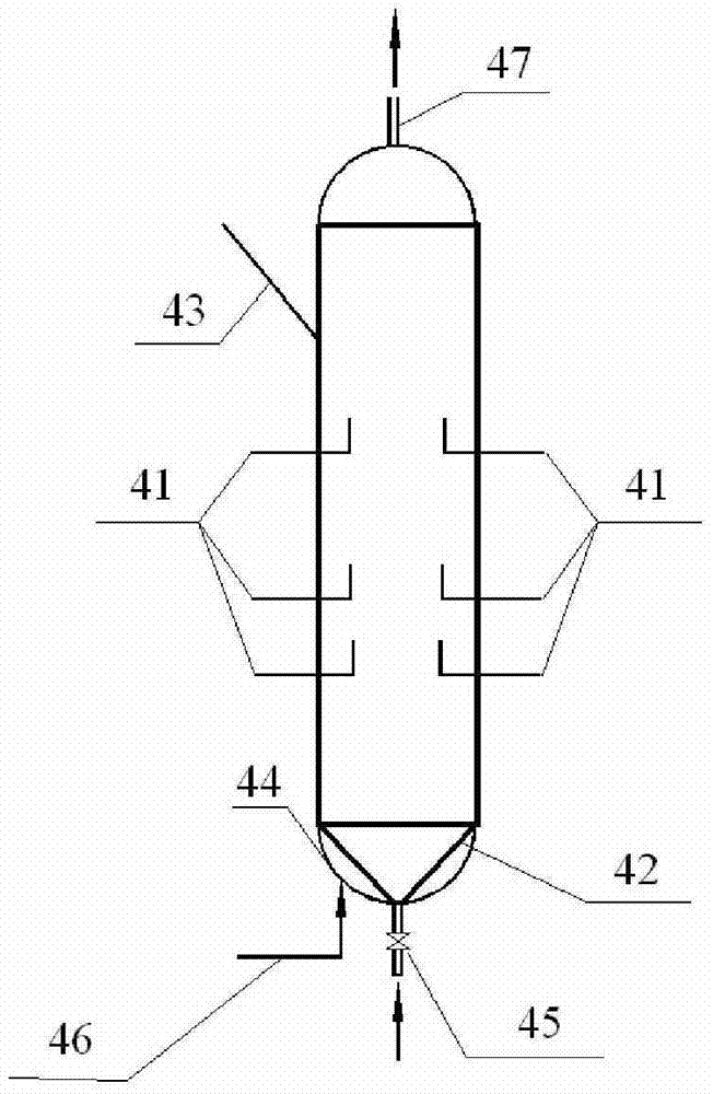
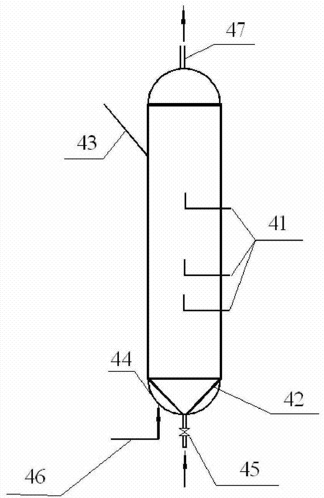
[0068] Such as figure 1 and figure 2 Shown, a kind of multi-jet fluidized bed reactor, described reactor comprises:

[0069] a reactor body, the interior of which forms a chamber;

[0070] A conical distribution plate 42 is located at the bottom of the reactor main body, forming an air chamber 44 with the wall of the bottom of the reactor main body;

[0071] The feed line 43 is arranged through the upper part of the reactor main body, and is in fluid communication with the chamber, so that the raw carbonaceous material enters the chamber;

[0072] The gasification agent pipeline 46 is arranged through the bottom of the reactor main body, and is opened to the gas chamber 44, so that the gasification agent enters the chamber through the conical distribution plate 42;

[0073] The bed gas distribution device 41 is arranged through the side wall of the reactor body and is in fluid communication with the chamber;

[0074] The discharge pipeline 47 is arranged through the top o...

Embodiment 2

[0080] A method for coal catalytic gasification using a multi-jet fluidized bed reactor, the carbonaceous material impregnated with the catalyst enters the reactor chamber through the feed line 43, and the gasification agent passes through the gasification agent line 46 from the gas chamber 44 through After the conical distribution plate 42 evenly distributes the gas, it enters the reactor chamber, and the gasifying agent and the carbonaceous material undergo a gasification reaction under the action of the catalyst; the gasifying agent is superheated steam and O 2The mixed gas in which the oxygen concentration is 5mol%, and the water-to-carbon molar ratio of the gasification agent to the carbonaceous material is 3.

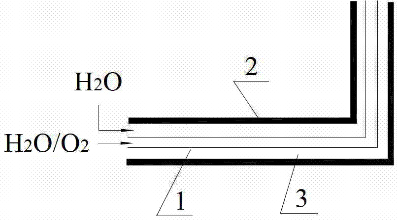
[0081] The central tube 1 of the jet tube as the bed gas distribution device 41 is fed with a mixture of oxygen and superheated steam, and superheated steam is passed into the annulus 3; the oxygen and carbonaceous materials undergo catalytic combustion to release ...

Embodiment 3

[0086] A method for coal catalytic gasification using a multi-jet fluidized bed reactor, the carbonaceous material impregnated with the catalyst enters the reactor chamber through the feed line 43, and the gasification agent passes through the gasification agent line 46 from the gas chamber 44 through The conical distribution plate 42 enters the reactor chamber after distributing the gas, and the gasification agent and the carbonaceous material undergo a gasification reaction under the action of the catalyst; the gasification agent is superheated steam, and the molar ratio of water to carbon is controlled to be 2.5;

[0087] The central tube 1 of the jet tube as the bed gas distribution device 41 is fed with a mixture of oxygen and superheated steam, and superheated steam is passed into the annulus 3; the oxygen and carbonaceous materials undergo catalytic combustion to release heat, which is a gasification reaction Provide heat; the superheated steam in the annulus 3 strengthe...


PUM


Abstract

The invention relates to a jet pipe, a fluidized bed reactor with the jet pipe and a coal catalyzing and gasifying method. A plurality of jet pipes which are in a bed-layer dispersing manner are adopted for feeding oxygen; the jet pipes are in a sleeve type structure; a central pipe is supplied with a mixture gas of oxygen and over-hot steam; the over-hot steam is supplied into annular spaces; the ratio of the oxygen to the over-hot steam is regulated to control the oxygen concentration to be within a certain range; the oxygen and a carbon material are mainly subjected to combustion strong exothermic reaction at a jet flow area; the released heat is used for providing heat for the gasification reaction in the reactor; the over-hot steam supplied into the annular spaces can intensity the internal circulation of carbon material granules, is subjected to heat exchange with a high-temperature gas at a central pipe area, and at the same time provide heat for the gasification heat absorption reaction in the annular spaces, so that partial high-temperature areas are prevented from happening through rapid heat exchange and gasification heat absorption reaction, and the happening rate that the jet pipe area has slag build-up is reduced.

Description

technical field [0001] The invention relates to the technical field of coal catalytic gasification, in particular to a jet tube, a fluidized bed reactor with the jet tube and a coal catalytic gasification method. The invention is not only applicable to the coal catalytic gasification process, but also applicable to the oxygen-gasification process of coal with low ash melting point and easy slagging and the co-gasification process of coal and biomass. Background technique [0002] With the rapid economic development and increasingly stringent environmental protection regulations, in the next ten years, my country's demand for natural gas, a clean energy source, will grow explosively. Although the production of natural gas has increased, it is far below the demand, and there is a contradiction between supply and demand. Increasingly prominent, the supply gap is increasing year by year. In view of the characteristics of my country's energy resource status of "rich in coal, low ...

Claims


Application Information

Patent Timeline
IPC IPC(8): C10J3/56
Inventor 毕继诚毛燕东李克忠康守国祖静茹
Owner ENN SCI & TECH DEV
Why Eureka
Try Eureka