Heating cooker
A technology for a cooker and a heating chamber, which is applied in the directions of heating mode, electric heating fuel, lighting and heating equipment, etc., can solve the problems of water droplets falling, the setting table of the heating cooker getting wet, etc.
- Summary
- Abstract
- Description
- Claims
- Application Information
AI Technical Summary
Problems solved by technology
Method used
Image
Examples
no. 1 approach
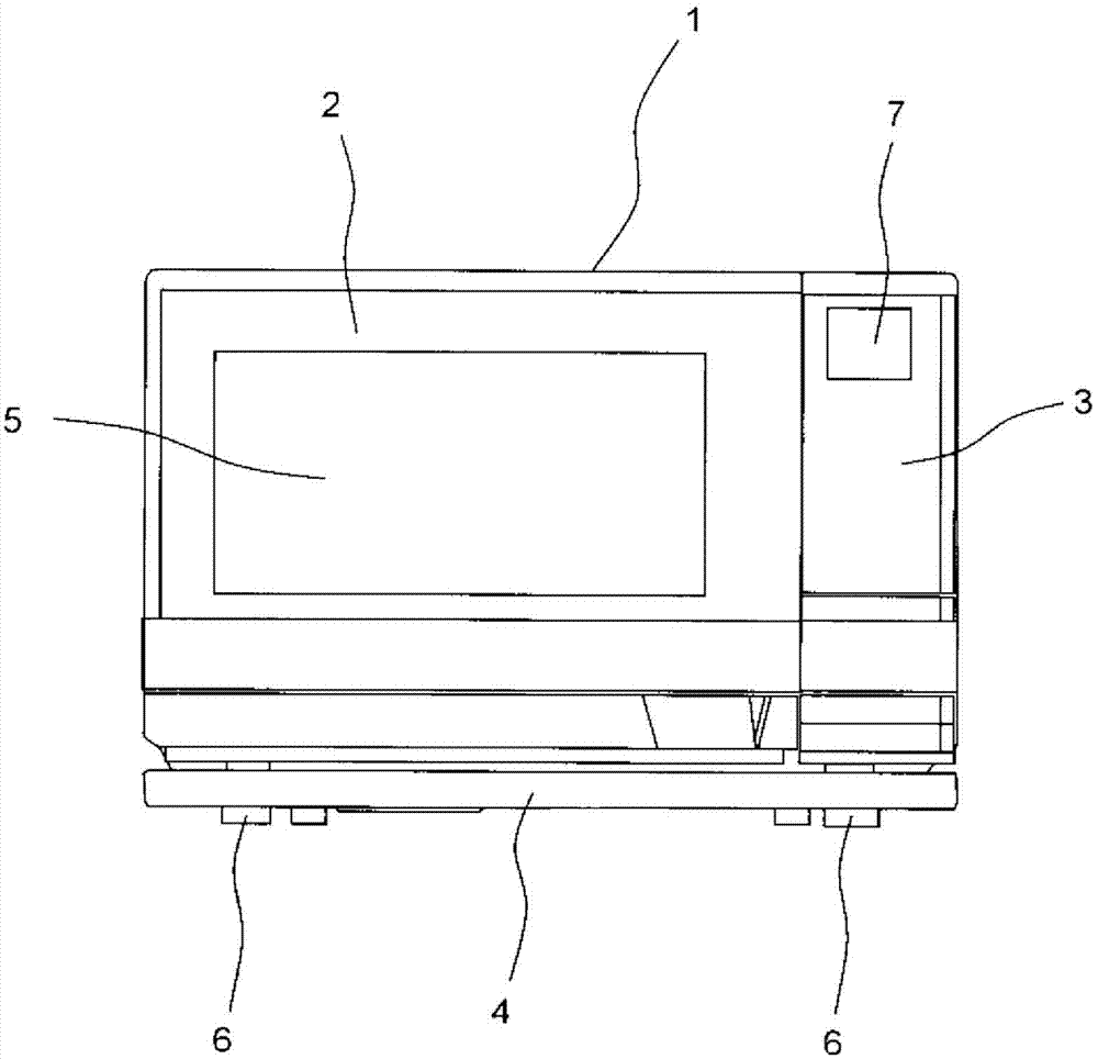
[0081] figure 1 It is a front view of the heating cooker of 1st Embodiment of this invention.
[0082] The heating cooker includes a housing 1 and a door 2 with a handle attached to the front side of the housing 1 . A heat-resistant glass 5 is installed substantially in the center of the handle-equipped door 2 . In addition, an operation panel 3 adjacent to the handle-equipped door 2 when closed is provided on the front surface side of the casing 1 . Moreover, the dew receiving container 4 is arrange|positioned below the handle-equipped door 2 and the operation panel 3. As shown in FIG. In addition, the door 2 with a handle is an example of the door of this invention, and the dew receiving container 4 is an example of the 2nd dew receiving part of this invention.
[0083] The operation panel 3 has a liquid crystal display unit 7 that displays a display corresponding to an operation. In addition, although a plurality of buttons etc. are provided on the operation panel 3, th...
no. 2 approach
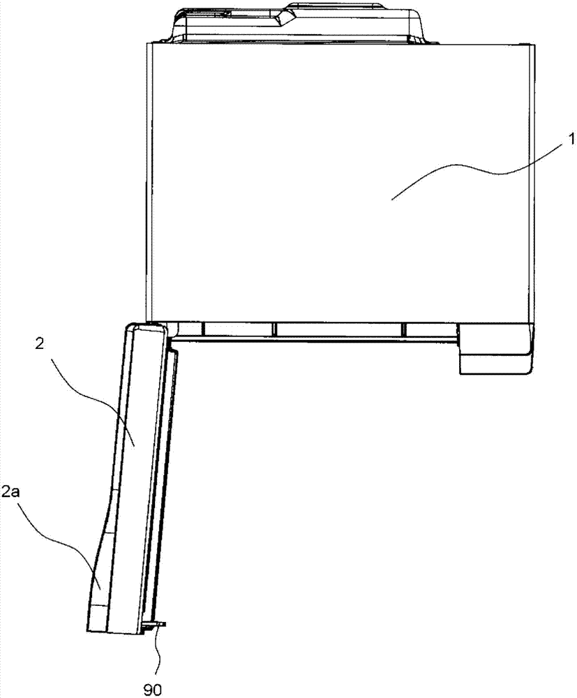
[0122] Figure 10 It is a schematic cross-sectional view in which the handle-equipped door 2 of the heating cooker according to the second embodiment of the present invention is fully opened (open state) as seen from the side. said Figure 10 The features of the heating cooker of the second embodiment are exaggerated. In addition, in Figure 10 in, right with Figure 9 Structural components that are the same as those of the first embodiment shown are labeled with Figure 9 The same reference numerals are used for the structural components and descriptions are omitted.
[0123] According to the heating cooker of the second embodiment, the casing 1 is inclined such that the rear side is lower than the front side. Specifically, the top surface of the casing 1 is inclined so as to form 0.3° to 0.7° (for example, 0.5°) with respect to the horizontal plane. Two front feet 6,6 (refer to figure 1 , figure 2 ), and two rear legs 219, 219 ( Figure 10 Only one is shown in ) to...
no. 3 approach
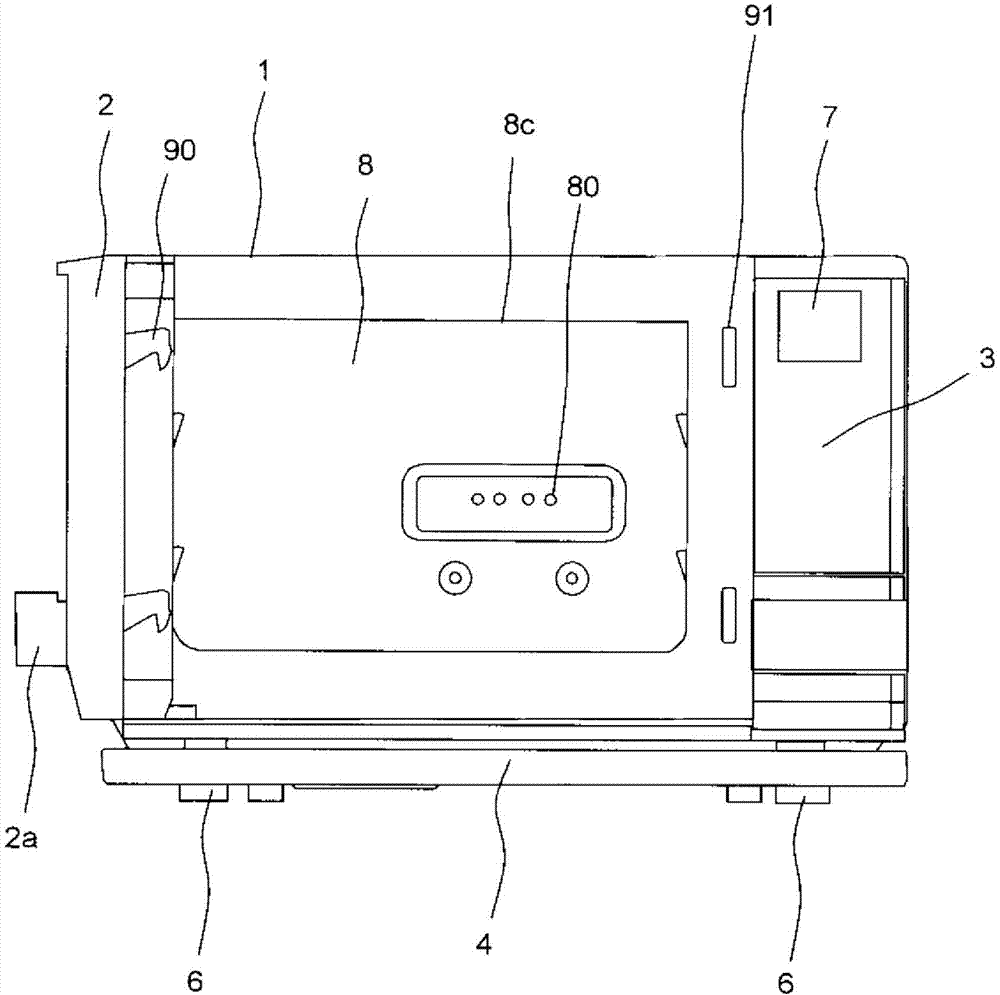
[0130] Figure 12 It is a schematic plan view in which the door 2 with a handle of the heating cooker according to the third embodiment of the present invention is in a fully opened state (open state) as seen from above. In addition, in Figure 12 in, right with figure 2 Structural components that are the same as those of the first embodiment shown are labeled with figure 2 The same reference numerals are used for the structural components and descriptions are omitted. In addition, in the following description, the same reference numerals as those of the first embodiment are attached to the same components as those of the first embodiment.
[0131] The heating cooker according to the third embodiment includes a fan-shaped plate member 300 in plan view, and the plate member 300 is attached to the lower edge of the handle-equipped door 2 and extends from the lower edge of the handle-equipped door 2 . to the lower part of housing 1. As indicated by a dashed-two dotted line...
PUM
 Abstract
Description
Claims
Application Information
 - R&D Engineer
- R&D Manager
- IP Professional
- Industry Leading Data Capabilities
- Powerful AI technology
- Patent DNA Extraction
Browse by: Latest US Patents, China's latest patents, Technical Efficacy Thesaurus, Application Domain, Technology Topic, Popular Technical Reports.
© 2024 PatSnap. All rights reserved.Legal|Privacy policy|Modern Slavery Act Transparency Statement|Sitemap|About US| Contact US: help@patsnap.com


