Narrow-gap welding nose with tilt angle device
A welding head and narrow gap technology, applied in welding equipment, electrode support devices, manufacturing tools, etc., can solve the problems of large welding torch, reduce meaning, increase groove gap, etc., to improve economic benefits and reduce manufacturing costs , the effect of small size
- Summary
- Abstract
- Description
- Claims
- Application Information
AI Technical Summary
Problems solved by technology
Method used
Image
Examples
Embodiment 1
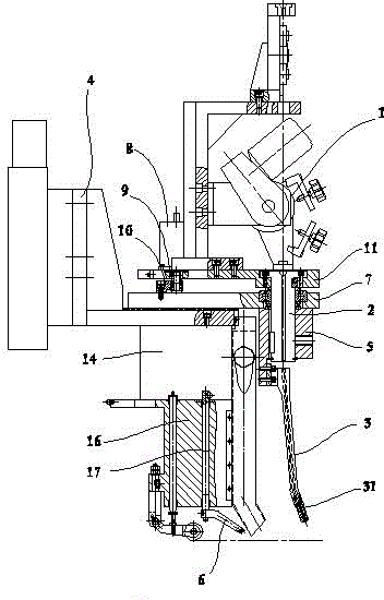
[0033] exist figure 1 In the first embodiment shown, the corner sleeve 5 is fixed to the guide wire rod 2; the swing angle mechanism is also provided with a fixed plate 7, a swing angle motor 8, and a driving gear 9 arranged on the swing angle motor shaft 1. The swing angle ring gear 10 and the swing plate 11 meshed with the driving gear; the fixed plate 7 and the connecting plate 4 are insulated and fixed; the guide wire rod 2 is pivoted with the fixed plate 7, and the swing angle gear The ring 10 is fixed with the fixed plate 7, the guide wire rod 2, the swing angle motor 8 and the wire feeding device 1 are all fixed on the swing plate 11, and the rotation axis of the swing angle ring gear and the The swing axis of the swing plate is coaxial with the guide wire rod.
[0034] When a certain side of the weld groove needs to be welded, the controller controls the rotation of the swing angle motor 8. Since the swing angle ring gear 10 is fixed on the fixed plate, the angle of t...
Embodiment 2
[0036] The corner cover 5 is fixed with the guide wire rod 2; the swing angle mechanism is also provided with a fixed plate 7, a swing angle motor 8, a driving gear 9 arranged on the swing angle motor shaft, and a pendulum meshed with the driving gear. Angle ring gear 10 and swing plate 11; said fixed plate 7 is insulated and fixed to said connecting plate 4; Fixed, the swing angle ring gear 10, the wire feeding device 1, the guide wire rod 2 and the swing plate 11 are fixed; and the rotation axis of the swing angle gear ring and the swing axis of the swing plate are connected with the guide wire Rod coaxial.
[0037] When a certain side of the weld groove needs to be welded, the controller controls the rotation of the swing angle motor 8, and drives the swing angle ring gear to rotate around the rotation axis by an angle through the driving gear. Since the swing angle ring gear 10 is fixed on the swing plate 11 , then the swing angle ring gear will drive the swing plate 11 t...
Embodiment 3
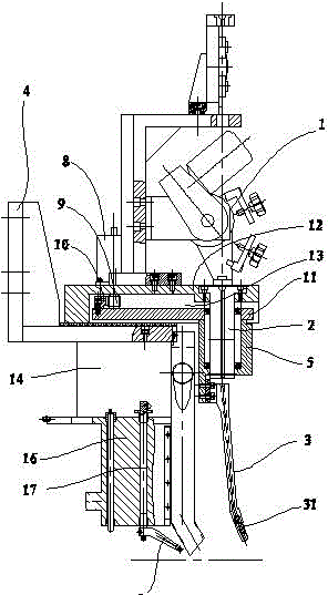
[0039] like figure 2 As shown, the corner sleeve 5 is pivoted with the guide wire rod 2 through bearings; the swing angle mechanism is also provided with a fixed plate 12, a swing angle motor 8, and a driving gear 9 arranged on the swing angle motor 8 shaft. 1. The swing angle ring gear 10 and the swing plate 11 meshed with the driving gear 9; the fixed plate 12 is insulated and fixed from the connecting plate 4, and a fan-shaped hole 13 is arranged in the middle; the wire feeding device 1 and the guide wire The rod 2 is fixed on the fixed plate 12, the swing plate 11 is set in the fan-shaped hole 13 of the fixed plate 12, and the corner sleeve 5 is located at the tip of the fan-shaped hole, and the swing angle ring gear 10 Fixed with the swing plate 11 and parallel to the arc of the fan-shaped hole, the swing angle motor 8 is fixed with the fixed plate 12 .
[0040] The difference between this embodiment and Embodiments 1 and 2 is that the swinging part of the welding torch...
PUM
 Abstract
Description
Claims
Application Information
 - R&D
- Intellectual Property
- Life Sciences
- Materials
- Tech Scout
- Unparalleled Data Quality
- Higher Quality Content
- 60% Fewer Hallucinations
Browse by: Latest US Patents, China's latest patents, Technical Efficacy Thesaurus, Application Domain, Technology Topic, Popular Technical Reports.
© 2025 PatSnap. All rights reserved.Legal|Privacy policy|Modern Slavery Act Transparency Statement|Sitemap|About US| Contact US: help@patsnap.com


