
Gas circuit structure for anesthesia respirator

A gas circuit and gas pipeline technology, applied in the direction of respirators, etc., can solve the problems of large impact, high pressure platform, impact, etc., and achieve the effect of repeated inhalation and uniform airway

Inactive Publication Date: 2013-05-01
BEIJING AEROSPACE CHANGFENG CO LTD
View PDF6 Cites 4 Cited by
  • Summary
  • Abstract
  • Description
  • Claims
  • Application Information

AI Technical Summary

Problems solved by technology

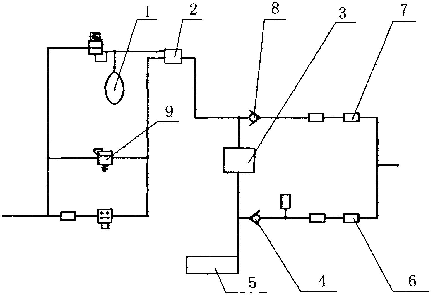
In the above-mentioned gas circuit structure, because the exhaled gas in the lungs flows to the driving gas outlet of the bellows to form a certain pressure, for different patients, the bellows is subjected to different pressures in the lungs, and the pressure changes with the pressure in the lungs of the patient, so that the outer tube of the bellows The marked scale cannot normally reflect the gas supply in the lungs, especially when it is applied to neonatal patients, and its influence is very large, and because there is a small positive or negative pressure in the overflow valve 9 in the bellows, this pressure has a great impact on The ventilation of the newborn has serious effects and can lead to hyperventilation or hypoventilation in the newborn
At the same time, because the softness of the bladder inside the bellows is difficult to control, the pressure platform cannot be reached well during the pressure control process, and it is easy to cause the pressure platform to be too high due to the elastic change of the bellows, making it difficult to reach the set pressure requirement

Method used


Image

  • Gas circuit structure for anesthesia respirator
  • Gas circuit structure for anesthesia respirator
  • Gas circuit structure for anesthesia respirator

Examples


Embodiment Construction

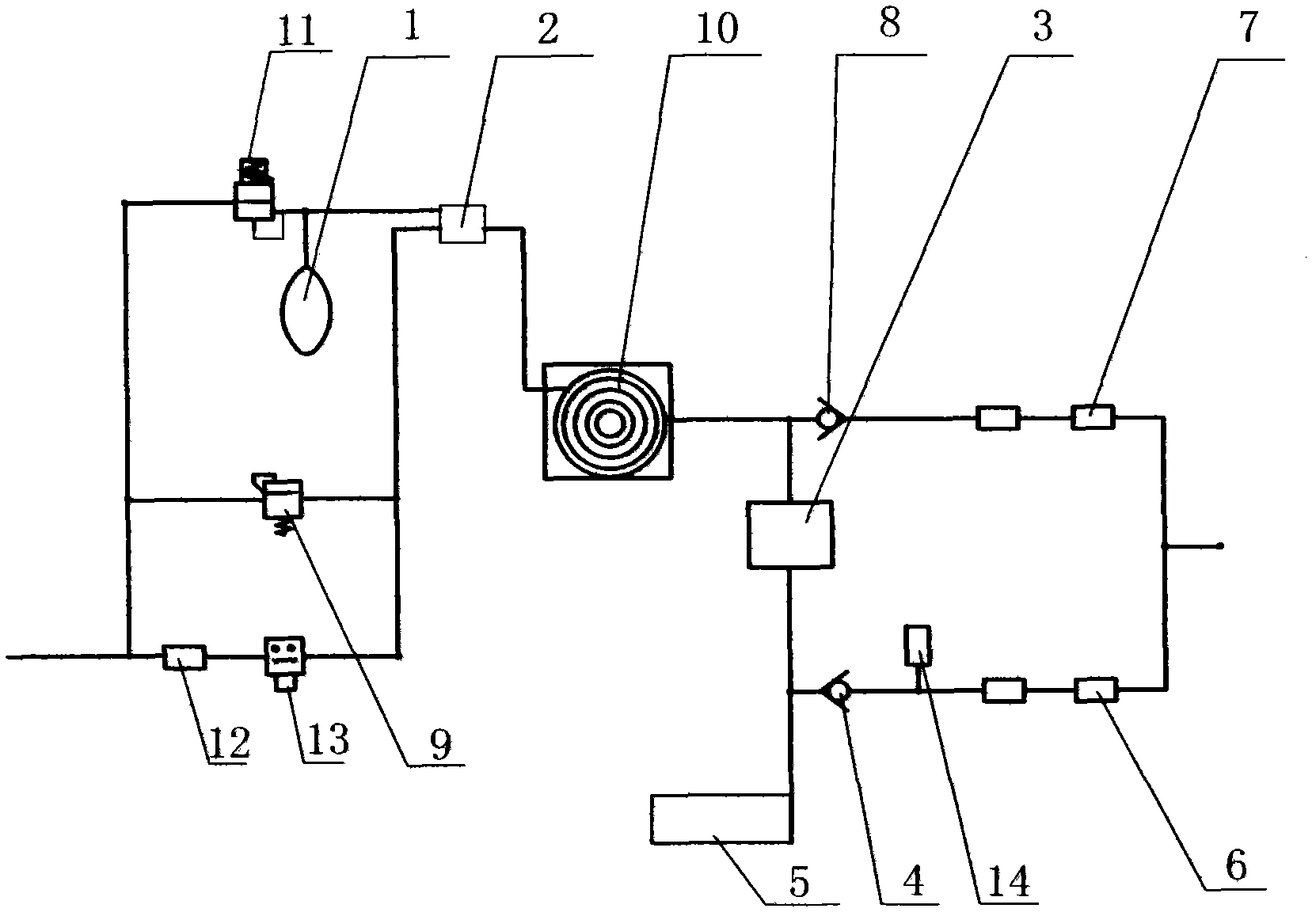
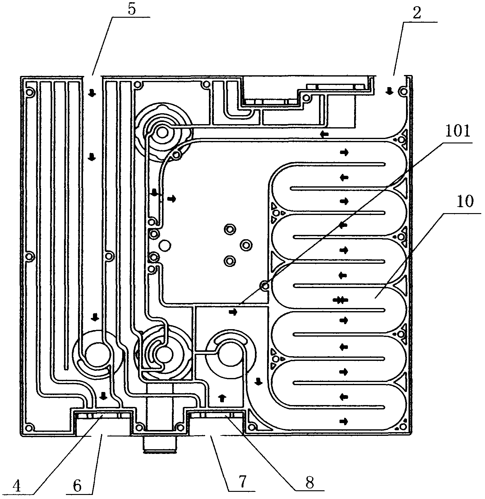
[0010] Anesthesia breathing system principle of the present invention is as figure 2 As shown, in addition to including the same bladder 1 as the prior art, the driving gas inlet 2, the fresh gas inlet 5, the inhalation check valve 4, the inhalation port 6, the exhalation one-way valve 8, the exhalation port 7, and the absorption tank 3, also includes a volume chamber 10. The skin bag 1 is connected to one end of the volume cavity 10 through an air path through the driving gas inlet 2, and the other end of the volume cavity 10 is connected to the gas outlet end of the exhalation one-way valve 8 through an air path. The air inlet end of the one-way valve 8 is connected to the exhalation port 7; the air path between the volume chamber 10 and the exhalation one-way valve 8 is connected to the air inlet of the absorption tank 3, and the absorption The gas outlet of the tank 3 and the fresh gas inlet 5 are connected to the suction port 6 via the suction one-way valve 4 through a ...


PUM


Abstract

The invention discloses a gas circuit structure for an anesthesia respirator, comprising a driving gas inlet, a fresh gas inlet, an inhale port, an inhale check valve, an exhale port, an exhale check valve, a tourill and a volume cavity, wherein a flexural gas pipeline is arranged in the volume cavity, the driving gas inlet is connected with one end of the flexural gas pipeline of the volume cavity, the gas outlet end of the exhale check valve is connected with the other end of the flexural gas pipeline of the volume cavity, and the gas inlet end of the exhale check valve is connected with the exhale port; a branch pipeline is arranged in the middle of the flexural gas pipeline of the volume cavity and is connected with the gas inlet end of the tourill, the gas outlet end of the tourill and the fresh gas inlet are connected with the gas inlet end of the inhale check valve, and the gas outlet end of the inhale check valve is connected with the inhale port.

Description

technical field [0001] The invention relates to an anesthesia ventilator, in particular to an air circuit structure of the anesthesia ventilator, and belongs to the technical field of medical equipment manufacturing. Background technique [0002] In the anesthesia breathing system, since the gas exhaled by the patient carries residual anesthesia gas, it is necessary to filter the gas exhaled by the patient to absorb and filter out the carbon dioxide, and then re-inhale it for the patient. Usually, a control system with a bellows device is used to achieve, such as figure 1 shown. When the patient is inhaling, the bladder 1 of the bellows is quickly filled with oxygen by the anesthesia machine, and the anesthetic gas is driven through the driving gas inlet 2 to flow to the inhalation one-way valve 4 through the absorption tank 3, and the fresh gas also flows to the inhalation through the fresh gas inlet 5 One-way valve 4, and enter patient's lung through suction port 6. Aft...

Claims


Application Information

Patent Timeline
Patent Type & Authority Applications(China)
IPC IPC(8): A61M16/01
Inventor 于涛刁俊
Owner BEIJING AEROSPACE CHANGFENG CO LTD
Learn More