
Coercivity performance determination device for coercivity distribution magnet

A judging device and coercive force technology, which can be used in magnetic properties measurement, measuring device, magnetic susceptibility measurement, etc., and can solve problems such as difficult to determine parts

Active Publication Date: 2013-04-24
TOYOTA JIDOSHA KK
View PDF7 Cites 2 Cited by
  • Summary
  • Abstract
  • Description
  • Claims
  • Application Information

AI Technical Summary

Problems solved by technology

[0007] However, since the coercive force has a distribution, it is difficult to determine whether each part has the required coercive force, and it is easy to understand that it takes time to confirm

Method used


Image

  • Coercivity performance determination device for coercivity distribution magnet
  • Coercivity performance determination device for coercivity distribution magnet
  • Coercivity performance determination device for coercivity distribution magnet

Examples


Embodiment Construction

[0060] Hereinafter, embodiments of the present invention will be described with reference to the drawings. In addition, the illustrated example is an example in which a protrusion is provided in the central region of the end face of the magnetic body. Of course, the form of the external magnetic field generating means, such as the protrusion, is provided in the region near the end and / or the end, and is not limited to the illustrated example.

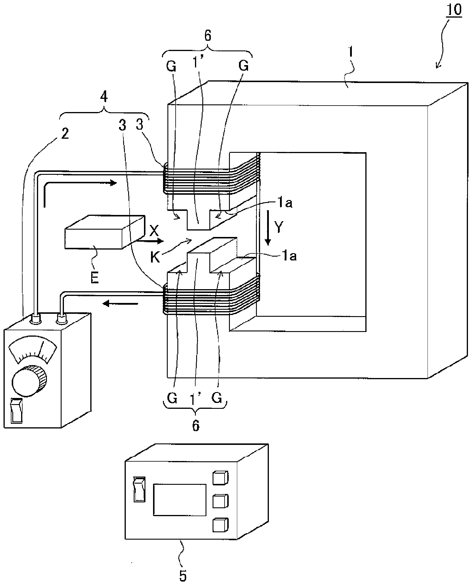
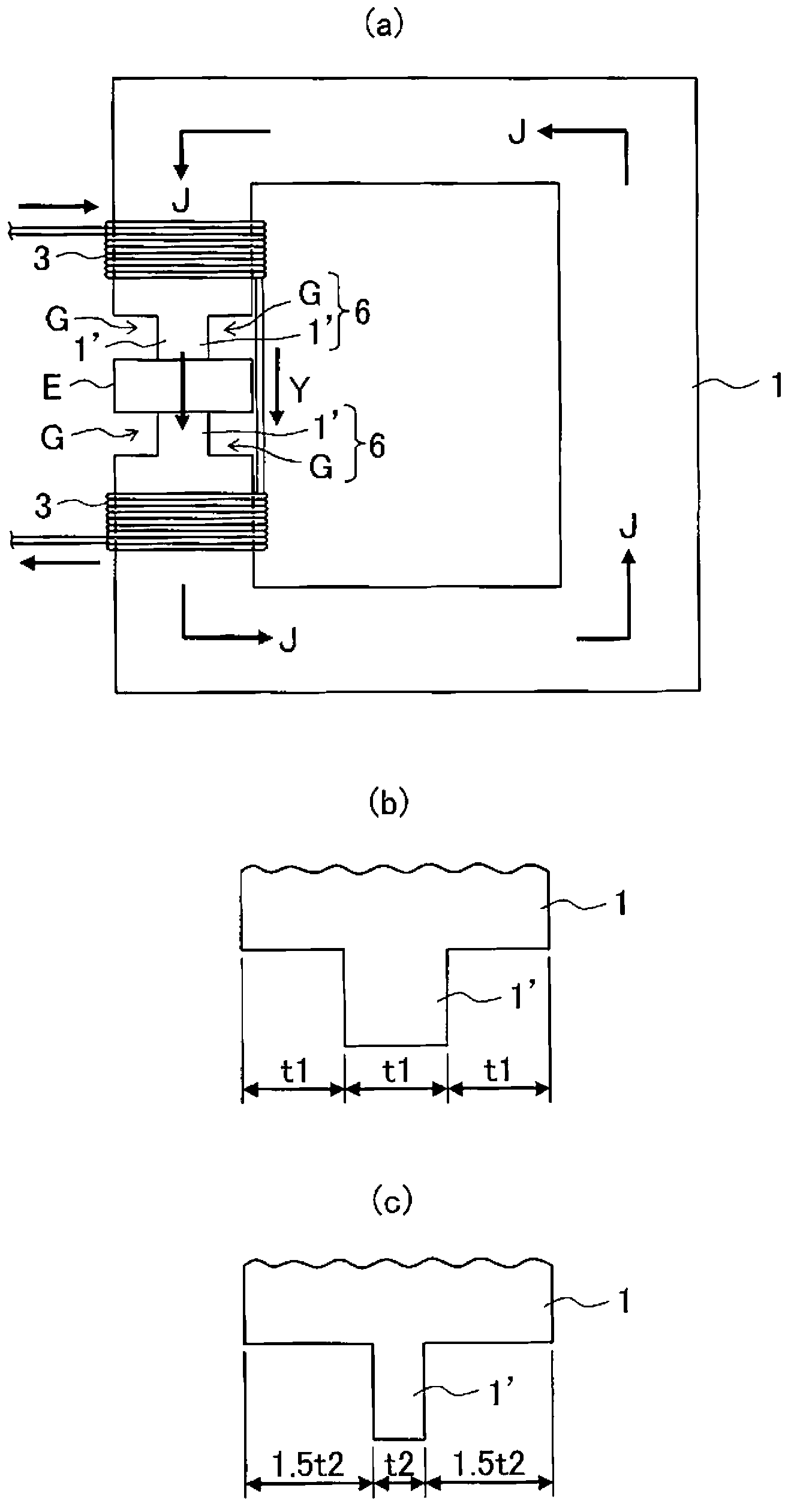
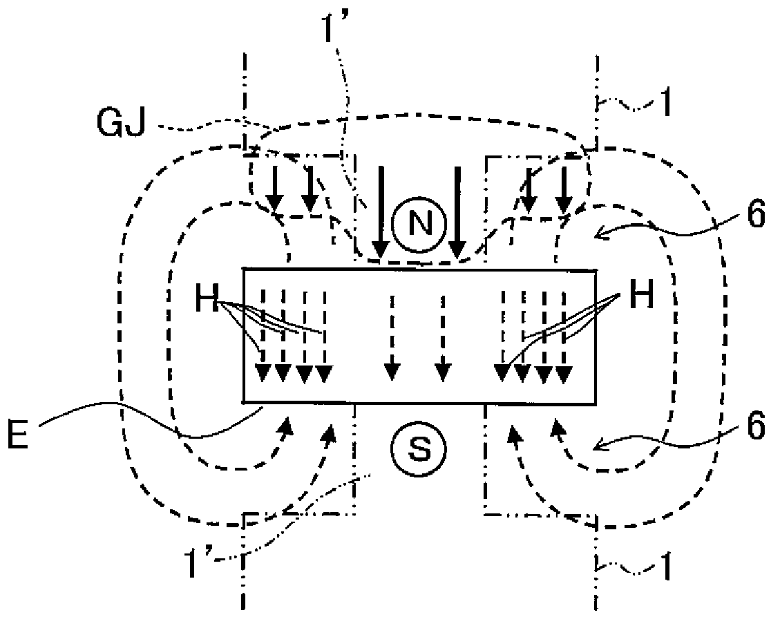
[0061] figure 1 It is a diagram schematically showing a coercive force performance determination device for determining the coercive force performance of the coercive force distribution magnet of the present invention, figure 2 a is stated in figure 1 A diagram showing a state in which a coercive force distribution magnet is installed in the coercive force performance determination device shown, and the magnetic force generated by the excitation unit flows in the magnetic circuit, figure 2 b. figure 2 Both c are diagrams illustra...


PUM


Abstract

Provided is a coercivity performance determination device for a coercivity distribution magnet, which is capable of determining whether or not each part of one coercivity distribution magnet has coercivity larger than or equal to required coercivity closely in a short time at the lowest possible test cost. This coercivity specification device is provided with an approximately C-shaped magnetic substance, an excitation means for producing a magnetic flow in the magnetic substance, and a magnetic fluxmeter for measuring the remaining magnetic flux amount of a coercivity distribution magnet, wherein projections are provided at corresponding positions of two end surfaces facing each other of the magnetic substance, the coercivity distribution magnet is sandwiched between the two projections to thereby form an annular magnetic path, an external magnetic field generation means is formed from a magnetic region formed by the projections and a nonmagnetic region formed by air therearound, an external magnetic field which is generated when magnetism flows through the projections is adjusted so that an opposing magnetic field configured from the sum of the external magnetic field and the demagnetizing field of the coercivity distribution magnet is equivalent to coercivity required for each part of the coercivity distribution magnet, and the remaining magnetic flux amount when the coercivity required for each part acts as the opposing magnetic field is measured by the magnetic fluxmeter to determine the coercivity performance.

Description

technical field [0001] The present invention relates to a coercive force performance judging device of a coercive force distributed magnet, which judges whether each part of a coercive force distributed magnet used in a motor has a coercive force higher than a required coercive force. Background technique [0002] The permanent magnet embedded in the rotor of an IPM motor or the like is required to have a coercive force capable of resisting demagnetization by an external magnetic field incident from the stator core side. [0003] Generally speaking, the external magnetic field acting on the permanent magnet is largest at the corner of the permanent magnet on the stator core side and smaller at the central side of the rotor core in plan view of the rotor embedded in the permanent magnet. [0004] On the other hand, for sintered permanent magnets, the metal particles used to improve the coercive force performance of the permanent magnets diffuse from the surface of the permane...

Claims


Application Information

Patent Timeline
Patent Type & Authority Applications(China)
IPC IPC(8): G01R33/12
CPCG01R33/123G01R33/16
Inventor 铃木雅文仲西真由美
Owner TOYOTA JIDOSHA KK
Learn More