


Quick Research
Generate reliable direction feasibility study reports for your R&D in just a few steps.

Technical Q&A
Discover and master advanced knowledge NOW. Basics, ideas, possibilities, all at once.

Find Solutions
As an expert in R&D theories, this can generate solutions to your technical problems instantly.

Evaluate Feasibility
Analyze your overall solution with one click, know your potential R&D risks in advance.

Monitor Landscape
Get weekly tech updates, stay abreast of the latest tech innovations and key insights.
Gas-liquid type intercooler
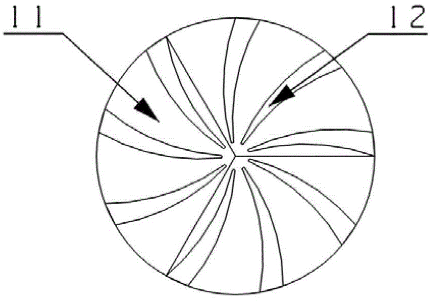
A gas-liquid cooler technology, applied to machines/engines, internal combustion piston engines, mechanical equipment, etc., can solve the problems of heat transfer effect to be improved and flow resistance, etc., to achieve enhanced heat transfer effect and reduced flow resistance , The effect of increasing the convection coefficient
- Summary
- Abstract
- Description
- Claims
- Application Information
AI Technical Summary
Problems solved by technology
Method used
Image


Examples
Embodiment 1
[0033] see Figure 1-7 , the gas-liquid intercooler of the present invention is mainly composed of an air inlet 1, an air inlet chamber 2, a tube plate 3, a shell 4, a heat exchange tube 5, a spiral baffle 6, a liquid inlet 7, and an exhaust chamber 8 , Exhaust port 9 and drain port 10.
[0034] see figure 1 and Figure 7 , the cross-section of the housing 4 is circular, its two ends are heads 14, and the two ends of its inner cavity are respectively provided with a tube plate 3, and the two tube plates 3 are respectively surrounded by the corresponding head 14 to form two air chambers. chamber, one of which is the air intake chamber 2, and the other is the exhaust chamber 8, and the two heads 14 are respectively provided with an air inlet 1 communicating with the air intake chamber 2 and an exhaust port 9 communicating with the exhaust chamber 8 . The space between the two tube sheets 3 in the shell 4 forms a heat exchange chamber, and the shell 4 at both ends of the heat...
Embodiment 2
[0042] see Figure 8 and Figure 9 , The difference between this embodiment and Embodiment 1 is that in this embodiment, the flow channel is 21 groups of circular through holes 15 distributed around the axis of the spiral spoiler 11, and each group of through holes 15 consists of a spiral One end of the spoiler 11 runs through to the other end; the diameter of the through hole 15 is 2 mm, and the 21 groups of through holes 15 are divided into three parts, the number is respectively 3, 6 and 12, and they are evenly distributed in the diameter of 4mm, 10mm and 16mm on the circumference.
[0043] The helix angle of the spiral spoiler 11 is 60°.
[0044] Embodiments other than the above in this embodiment are the same as in Embodiment 1.
PUM
| Property | Measurement | Unit |
|---|---|---|
| Helix angle | aaaaa | aaaaa |
| Outer diameter | aaaaa | aaaaa |
| Outer diameter | aaaaa | aaaaa |
Abstract
Description
Claims
Application Information
 - R&D Engineer
- R&D Manager
- IP Professional
- Industry Leading Data Capabilities
- Powerful AI technology
- Patent DNA Extraction
Browse by: Latest US Patents, China's latest patents, Technical Efficacy Thesaurus, Application Domain, Technology Topic, Popular Technical Reports.
© 2024 PatSnap. All rights reserved.Legal|Privacy policy|Modern Slavery Act Transparency Statement|Sitemap|About US| Contact US: help@patsnap.com