A liquid storage tank with stable liquid output flow
A technology of output flow and liquid storage tank, which is applied in the direction of transportation and packaging, containers, packaging, etc., can solve the problems of low output liquid flow control accuracy and poor output flow stability, and achieve stable liquid level, stable liquid output flow, and control high precision effect
- Summary
- Abstract
- Description
- Claims
- Application Information
AI Technical Summary
Problems solved by technology
Method used
Image
Examples
Embodiment 1
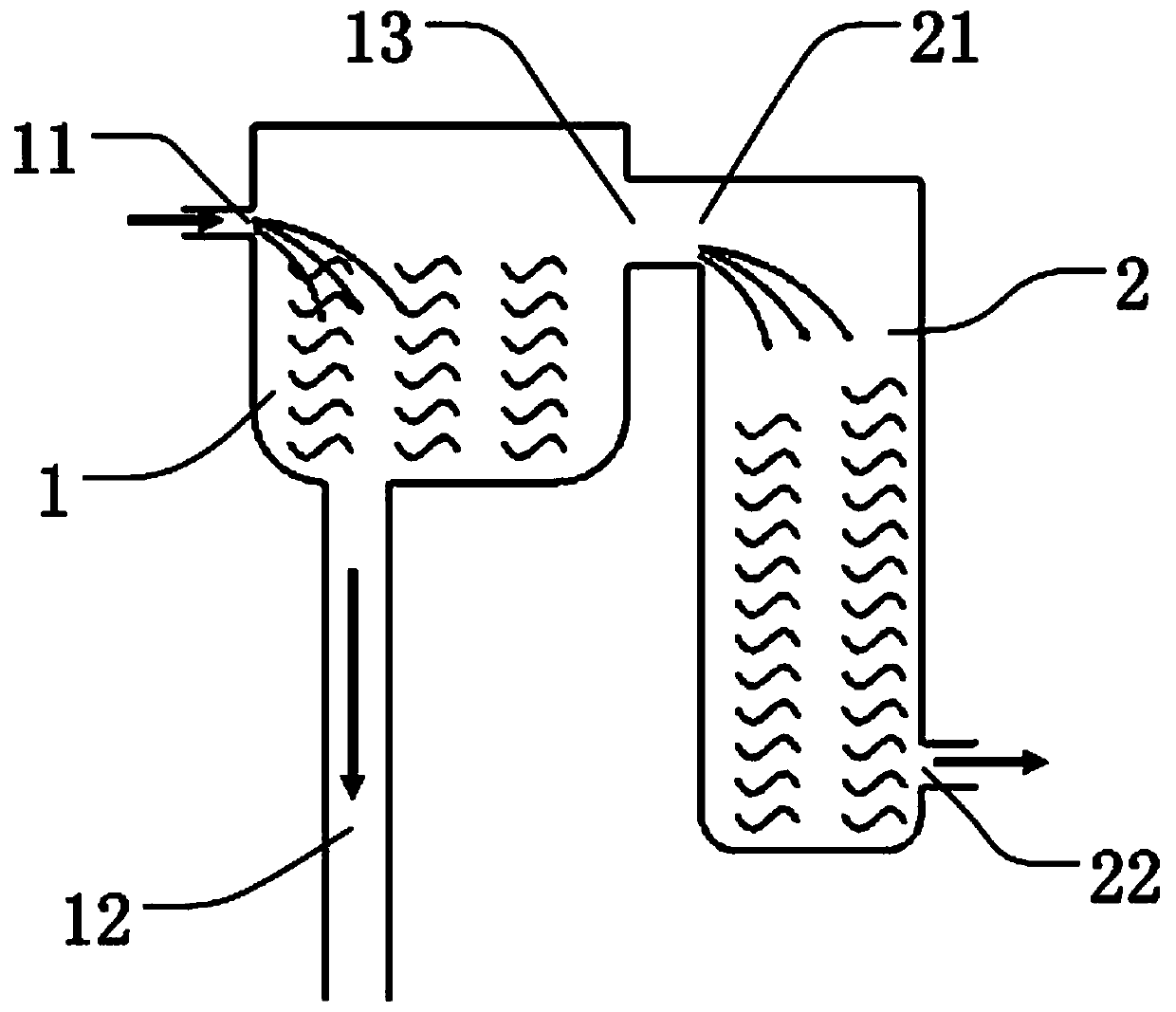
[0026] like figure 1 It is a structural schematic diagram of Embodiment 1 of the present invention, figure 1 Shown in is a container for stabilizing liquid output flow, including a main tank 1 for storing liquid; main tank 1 is provided with a main tank liquid inlet 11 for inputting liquid, and a main tank for discharging liquid The liquid discharge port 12 also includes a limiting device for limiting the liquid level in the main tank 1 .
[0027] A secondary tank 2 is provided outside the main tank 1, which is used as the limit device; a limit port 13 is provided on the side wall of the main tank 1, which is used to limit the liquid level in the main tank 1; a secondary tank 2 is provided with a The tank liquid inlet 21 is connected to the limit port 13, which is used to introduce the liquid in the main tank 1 whose liquid level is higher than the limit port 13 to the auxiliary tank 2; the auxiliary tank 2 is provided with a secondary tank drain port 22 for Drain the liquid...
Embodiment 2
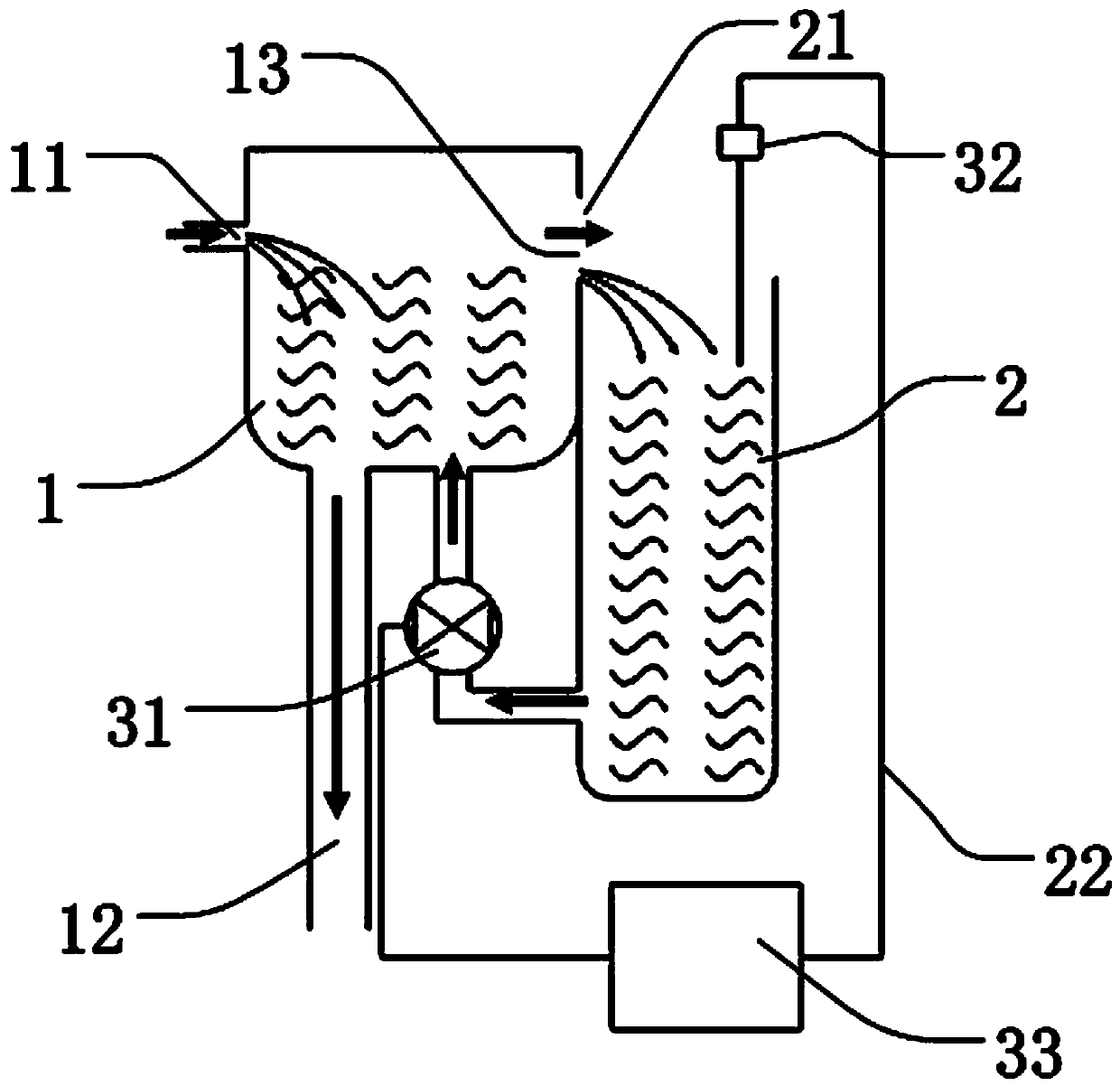
[0029] figure 2 It is a structural schematic diagram of Embodiment 2 of the present invention, such as figure 2 As shown, most of the technical solutions of embodiment 2 are the same as those of embodiment 1, and the technical difference is that the main tank 1 is provided with a second liquid inlet 14 of the main tank, which is connected to the liquid outlet of the auxiliary tank through a liquid pump 31 22, used to introduce the liquid in the auxiliary tank 2 to the main tank 1, so that the liquid level in the auxiliary tank 2 will not be too high to cause liquid overflow, while avoiding liquid waste; the auxiliary tank 2 is provided with a liquid level sensor 32 for obtaining Liquid level status information in the auxiliary tank 2; the liquid inlet 21 of the auxiliary tank can be connected to the limit port 13 through a conduit, and the liquid inlet 21 of the auxiliary tank can also be the limit port 13. At this time, the sides of the main tank 1 and the auxiliary tank 2 ...
Embodiment 3
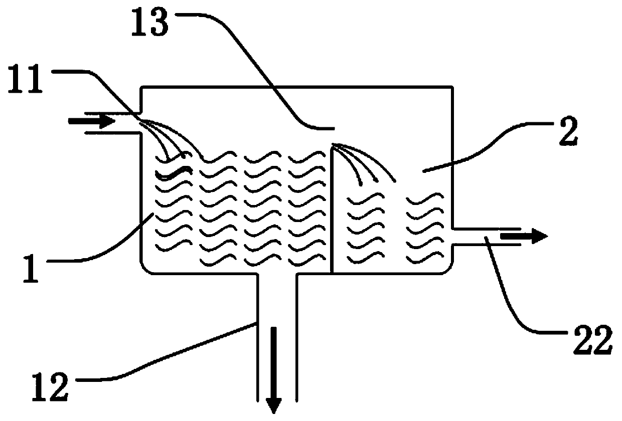
[0032] like image 3 It is a schematic structural diagram of Embodiment 3 of the present invention, image 3 Shown in is a container for stabilizing liquid output flow, including a main tank 1 for storing liquid; main tank 1 is provided with a main tank liquid inlet 11 for inputting liquid, and a main tank for discharging liquid The liquid discharge port 12 also includes a limiting device for limiting the liquid level in the main tank 1 .
[0033] A sub-box 2 is provided inside the main box 1, which is used as the limiting device. Part of the side wall in the sub-box 2 can be the same as the main box 1, that is to say, the sub-box 2 can be a part isolated from the main box 1 , can also be an independent container; the upper surface of the auxiliary tank 2 is provided with a limit port 13, which is used to limit the liquid level height in the main tank 1, and the limit port 13 should be as large as possible, preferably the entire upper surface of the auxiliary tank 2 Both are...
PUM
 Abstract
Description
Claims
Application Information
 - R&D
- Intellectual Property
- Life Sciences
- Materials
- Tech Scout
- Unparalleled Data Quality
- Higher Quality Content
- 60% Fewer Hallucinations
Browse by: Latest US Patents, China's latest patents, Technical Efficacy Thesaurus, Application Domain, Technology Topic, Popular Technical Reports.
© 2025 PatSnap. All rights reserved.Legal|Privacy policy|Modern Slavery Act Transparency Statement|Sitemap|About US| Contact US: help@patsnap.com


