
Analog flue gas mixing device based on high temperature humidity generator

A technology of humidity generator and simulated flue gas, which is applied in the direction of gas and gas/steam mixing, mixer, mixing method, etc., which can solve the inconsistency of flue gas temperature, humidity and sulfur content, failing to meet the requirements of flue gas simulation, Correct problems such as large changes in the environment of the humidity probe to achieve the effects of avoiding mutual interference or influence, fast response speed, and small fluctuations in accuracy

Active Publication Date: 2013-04-24
NANJING ASSEN ENVIRONMENT TECH
View PDF4 Cites 10 Cited by
  • Summary
  • Abstract
  • Description
  • Claims
  • Application Information

AI Technical Summary

Problems solved by technology

[0003] Similar products on the market are either inconsistent with the flue gas temperature, humidity and sulfur content in the flue, and cannot meet the flue gas requirements in the simulated flue; or the accuracy of the reference instrument does not meet the requirements; or it is used to correct the environmental changes of the humidity probe Larger, difficult to calibrate, etc.; because various parameters of standard humidity are greatly affected by the environment, how to maintain a relatively stable and continuous measurement environment, so that the prepared high-temperature simulated flue gas is closer to the actual situation, and realize Testing flue gas performance in the laboratory is a major problem in simulating flue gas mixing devices

Method used


Image

  • Analog flue gas mixing device based on high temperature humidity generator
  • Analog flue gas mixing device based on high temperature humidity generator
  • Analog flue gas mixing device based on high temperature humidity generator

Examples


Embodiment 1

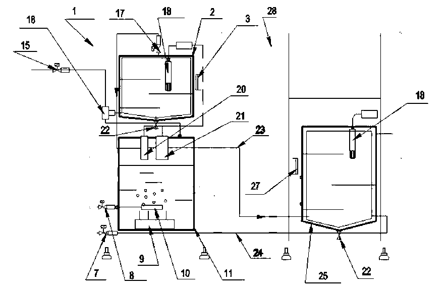
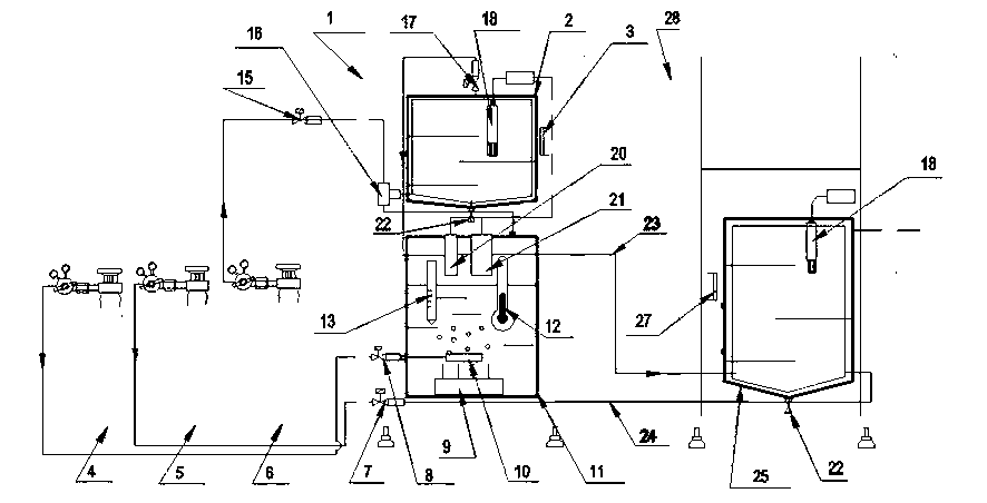
[0030] Such as figure 1 As shown, the simulated flue gas mixing device based on the high-temperature humidity generator of this patent is mainly divided into two parts: the high-temperature standard humidity generating device 1 and the flue gas mixing device 28, including the gas storage tank 2, the standard gas flow meter 7, Moisture gas flow meter 8, bubbler 10, constant temperature water tank 11, dry gas flow meter 15, tee joint 16, mixed moisture flow meter 17, small detection chamber 20, medium detection chamber 21, mixed moisture pipeline 23 , standard gas heating pipeline 24, mixed gas tank 25, and dew point meter 18; the wet gas flowmeter 8 is connected to the foamer 10 arranged inside the constant temperature water tank 11, and the three-way joint 16 is respectively connected to the constant temperature water tank 11 outlet and the dry gas flow rate The meter 15 is connected to the inlet of the gas storage tank 2, and the outlet of the gas storage tank 2 is connected ...

Embodiment 2

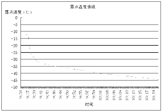
[0071] The performance test of the high temperature standard humidity generating device 1 adopts the CEMS DAS laboratory test software developed by Nanjing Essen Environmental Technology Co., Ltd. The test steps are as follows:

[0072] step 1 : Set the test environment: indoor, no vibration, room temperature 25°C;

[0073] The parameters of the high temperature standard humidity generating device 1 are set as follows:

[0074] The temperature control meter of the constant temperature water tank is set at 48°C

[0075] The temperature control meter of the detection chamber is set at 54°C

[0076] Sampling interval: 15s

[0077] step 2 : Reliably connect the wet gas tank 4 and the dry gas tank 6 to the wet gas flowmeter 8 and the dry gas flowmeter 15 interfaces in the high temperature standard humidity generating device 1 respectively. The technical indicators of the above two gases are as follows:

[0078] 1) Humidity: Compressed air: O 2 : 21%; ...

Embodiment 3

[0102] The actual usage test of the simulated flue gas mixing device based on the high-temperature humidity generator of this patent is as follows:

[0103] The temperature of the calibration gas heating pipeline 24 is maintained at 150°C, and the temperature inside the mixed gas tank 25 is set to not be lower than 120°C. Use a multi-component analyzer to measure SO at the gas outlet of the high-temperature mixed gas tank 25 2 concentration and humidity to verify the loss of SO2 and the stability of the humidity of the mixed gas during the gas mixing process, see Figure 9 (Table 1), Figure 10 (Table 2).

[0104] Testing requirements:

[0105] 1) Inlet humidity: 10.5Vol%, 5.5Vol%, respectively.

[0106] 2) Select the standard gas to simulate SO 2 Pollution gas, the main component is SO 2 The concentration is 1000PPM, the rest is N 2 .

[0107] 3) There are two sets of test settings, and the test temperatures are 100°C and 150°C respectively.

[0108] 4) Mix the st...


PUM


Abstract

The invention belongs to the field of a flue gas monitoring and testing device, and particularly relates to an analog flue gas mixing device based on a high temperature humidity generator. The analog flue gas mixing device based on the high temperature humidity generator comprises a gas tank (2), a standard-gas flow meter (7), a moisture flow meter (8), a foam generator (10), a constant temperature water tank (11), a dry gas flow meter (15), a T-junction (16), a mixed moisture flow meter (17), a small testing case (20), a medium testing case (21), a mixed moisture pipeline (23), a standard-gas heating pipeline (24), a mixing gas tank (25), and a dew-point instrument (18). When the analog flue gas mixing device simulates flue gas mixture, the analog flue gas mixing device based on the high temperature humidity generator utilizes a mixed flow method to solve the problem that how to simulate a high temperature and high humidity state of the flue gas at first, and thus can simulate high temperature moisture with 0% to 30% volume occurred at the temperature of up to 165 degrees, and then adds the standard-gas with the high temperature moisture to achieve a higher gas composition and humidity accuracy based on the traceably calibrating function of the precision mirror surface dew-point instrument, so that an instrument calibration and other experiments can be achieved without being on the scene of the flue, and therefore the labor intensity of the staff is reduced and great convenience is brought for experimenters.

Description

technical field [0001] The invention belongs to the field of flue gas monitoring test equipment, in particular to a simulated flue gas mixing device based on a high-temperature humidity generator. Background technique [0002] The flue gas in the flue is often a high-temperature, high-humidity sulfur-containing gas. Thermal power generation companies, oil refineries, some chemical plants, electric power research units, and environmental protection departments often have to simulate the flue gas in the flue for instrument calibration and other experiments. Electrical, electronic, instrumentation and other products, parts and materials are often subjected to high-temperature and high-humidity tests or constant tests to check whether the quality, reliability, storage, transportation and use of products, parts and materials in harsh environments meet the requirements, etc. . [0003] Similar products on the market are either inconsistent with the flue gas temperature, humidity...

Claims


Application Information

Patent Timeline
IPC IPC(8): B01F5/00B01F3/02B01F15/02B01F15/04B01F15/06G01N33/00B01F23/10
Inventor 刘德允范黎锋陈莹章曙孙明伟董伟
Owner NANJING ASSEN ENVIRONMENT TECH
Learn More