Roam mode realizing method in three-dimensional scene simulation system

A simulation system and 3D visual technology, applied in the field of roaming mode design, can solve problems such as complex implementation methods, limited viewpoint and viewing angle range, lack of vividness, etc., and achieve the effect of convenient browsing

Inactive Publication Date: 2013-04-17
CASIC SIMULATION TECHNOLOGY CO LTD
View PDF0 Cites 25 Cited by
  • Summary
  • Abstract
  • Description
  • Claims
  • Application Information

AI Technical Summary

Problems solved by technology

[0007] Through the comparison in the above table, we can find that the first type of mode is easy to operate, and the routine operation of scene roaming can be completed only by using the mouse. In the case of inspection, regardless of the size of the scene, the content of the entire scene can be browsed conveniently and quickly; however, the implementation method of this mode is complicated, it is impossible to quickly switch between scenes and the subjective immersion to the user is poor
The second type of mode can bring users a good sense of immersion. Users can manipulate the first-person point of view through keyboard and mouse operations, which is often used in role-playing 3D e-sports games; Can browse the situation near the viewpoint position, but cannot conveniently view the overall scene distribution
The third type of mode is simple to implement, easy to operate and accurate in positioning; however, its main disadvantage is that it cannot express the positional relationship between the two points before and after switching and lacks vividness
Summarizing the actual development experience, we can know that a prominent problem in the design process of roaming mode is that it is difficult to take into account the macro and micro display in complex scenes at the same time.

Method used


Image

  • Roam mode realizing method in three-dimensional scene simulation system
  • Roam mode realizing method in three-dimensional scene simulation system
  • Roam mode realizing method in three-dimensional scene simulation system

Examples


Embodiment Construction

[0044] In one embodiment of the present invention, the roaming mode implementation method in the 3D scene simulation system includes the following steps 1 to 4, and in another preferred embodiment, also includes the following step 5.

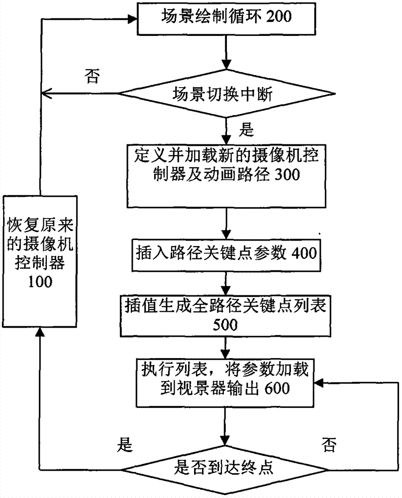
[0045] Step 1: Trigger the interruption of the scene drawing cycle, define and load a new camera controller and animation path.

[0046] This walkthrough mode is primarily aimed at scene cuts, where the camera is in an automatically executed draw loop, so the user has no control over the viewport position and angle at this point. However, outside the switching process, the user needs to obtain the control right of the camera so as to quickly browse the scene position of interest. Therefore, the scene roaming controller under normal circumstances still adopts the roaming mode of the overall operation class or the first person class, and the roaming mode in the present invention will take over the viewpoint control in a specific situation as a con...


PUM


Abstract

The invention relates to a roam mode realizing method in a three-dimensional scene simulation system. The roam mode realizing method comprises the following steps of: 1, triggering the interruption of a scene paint cycle, defining and loading a new camera controller and an animation path; 2, dynamically obtaining positions of visual points interested by a user in real time, calculating to obtain corresponding key nodes and inserting the key nodes in key point lists of the defined animation path; 3, interpolating to generate all nodes of the path and inserting the nodes into the key point list; and 4, executing the animation path comprising all key point lists. A camera in a scene is used for capturing the nodes interested by the user along the real-time calculated path, and thus the roam mode realizing method has at least one of the advantages that the switching of scene observation visual points is completed by using a more vivid mode, the positional relation of two points before and after switching can be more clearly explained, and the scene integral position distribution is taken into account while the specific interested positions are concerned.

Description

technical field [0001] The invention relates to the design of a roaming mode in a three-dimensional visual simulation system, in particular to a method for realizing the roaming mode in a three-dimensional visual simulation system, which is especially suitable for browsing and roaming of large-scale scenes such as terrain and landform. Background technique [0002] The visual simulation system is a comprehensive utilization of virtual reality, computer simulation, optical imaging and other technologies, through the computer 3D visual simulation of the target object, to provide users with a practical, convenient, shocking and realistic, information-rich visual display and management platform. Immersive spatial 3D visual experience. This technology is widely used in the visual display and management of engineering information such as large-scale projects, urban planning, real estate projects, water, oil, gas and electricity pipeline networks. Roaming mode refers to the specif...

Claims


Application Information

Patent Timeline
Patent Type & Authority Applications(China)
IPC IPC(8): G06T19/00
Inventor 杨方廷韩哲宿春慧刘玉明管文艳曹伟伟
Owner CASIC SIMULATION TECHNOLOGY CO LTD
Why Eureka
Try Eureka