
Device and method for monitoring dynamic torque of frameless torque motor in suspension state

A torque motor and dynamic torque technology, applied in the field of measuring devices, can solve the problems of inability to accurately measure the real-time dynamic torque of torque motors, inaccurate dynamic torque measurement, and inability to measure.

Inactive Publication Date: 2015-08-26
NORTH CHINA UNIVERSITY OF TECHNOLOGY
View PDF2 Cites 0 Cited by
  • Summary
  • Abstract
  • Description
  • Claims
  • Application Information

AI Technical Summary

Problems solved by technology

The strain gauge torque sensor measures the torque by measuring the deformation of the elastic element through the strain gauge. This measurement method is greatly affected by the material and shape of the elastic shaft. In principle, it is difficult to continue to improve the resolution, and this test method And the device is only suitable for analyzing and measuring the static torque of the material under the condition of static force
For the non-contact sensor to measure the torque, the magnetoelectric sensor is affected by the ambient temperature and the external magnetic field, the sensitivity will change and the measurement error will occur. For the micro torque, the error is usually large or even impossible to measure. The above two methods, due to the inability Accurately measure angular acceleration and frictional torque, so there is the defect of inaccurate dynamic torque measurement, and the existing technology cannot accurately measure the real-time dynamic torque output by the torque motor
At present, there is no device and method suitable for monitoring the dynamic torque of the frameless torque motor in the suspension state, and the data of dynamic torque is of great significance for calibrating the performance of the frameless torque motor in the suspension state, so it is required to adopt a new The principle realizes real-time measurement of dynamic torque

Method used


Image

  • Device and method for monitoring dynamic torque of frameless torque motor in suspension state
  • Device and method for monitoring dynamic torque of frameless torque motor in suspension state
  • Device and method for monitoring dynamic torque of frameless torque motor in suspension state

Examples


Embodiment Construction

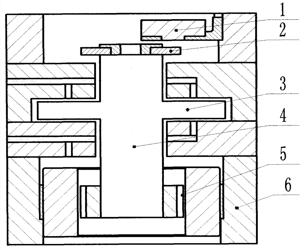
[0032] Such as figure 1 As shown, it is a schematic diagram of the installation structure when the present invention is used to monitor the dynamic torque of the frameless torque motor under the air-floating state. The measured frameless torque motor (5) directly drives the air-floating main shaft (4), and the air-floating main shaft (4) passes through The support of the air bearing (3) realizes a nearly frictionless suspension state, the circular grating disk (2) is fixedly connected with the coaxial line of the air bearing main shaft (4), and rotates synchronously with the air bearing main shaft (4); the reading head (1 ) is aligned with the grating ruler on the circular grating disc (2), so as to ensure that the dynamic angular displacement data of the air bearing spindle (4) driven by the frameless torque motor (5) can be collected correctly in real time; the reading head (1) passes The data line forms an electrical connection with the signal conversion and preprocessing c...


PUM


Abstract

The invention relates to a device for monitoring a dynamic torque of a frame-fee torque motor under a suspension state, and the device comprises a non-contact photoelectric encoder which is installed on the frame-free torque motor, and a signal conversion and pretreatment circuit, a high-speed data collection card and a calculation analysis data unit, which are installed inside a principal computer; the non-contact photoelectric encoder comprises a circular grating disk and a reading head; the circular grating disk is fixedly and coaxially connected with a rotary part of the frame-free torque motor, and the reading head is fixedly connected onto a fixed seat; and the reading head can collect dynamic angular displacement data of the rotary part of the frame-free torque motor in real time, and a dynamic torque output value and a rotation speed of the frame-free torque motor can be displayed in real time through the signal processing and data analysis.

Description

technical field [0001] The invention relates to a measuring device for real-time monitoring of the dynamic torque of a frameless torque motor in a suspended state. Background technique [0002] The torque motor has the characteristics of low speed, high torque, strong overload capacity, fast response, good characteristic linearity, and small torque fluctuation. It can directly drive the load without the intermediate transmission mechanism, thereby improving the operating accuracy of the system. Therefore, it is widely used in industrial fields such as textile, wire and cable, metal processing, paper making, rubber, plastic and printing machinery. [0003] The torque output value is a typical parameter that characterizes the performance and working state of the torque motor drive, and its measurement has important significance. However, the existing method for measuring the output torque of the torque motor is only suitable for measuring the static torque, even if the dynami...

Claims


Application Information

Patent Timeline
Patent Type & Authority Patents(China)
IPC IPC(8): G01L3/00
Inventor 张从鹏罗学科李美波
Owner NORTH CHINA UNIVERSITY OF TECHNOLOGY
Learn More