
System and method of translating a relational database into an XML document and vice versa

a relational database and document technology, applied in the field of system and method of translating a relational database into an xml document, can solve the problems of inability to realize potential, laborious process, tedious and error-prone, etc., and achieve the effect of improving database performance and being convenient to us

Active Publication Date: 2008-12-25
FONG JOSEPH S P
View PDF31 Cites 77 Cited by
  • Summary
  • Abstract
  • Description
  • Claims
  • Application Information

AI Technical Summary

Benefits of technology

"The present invention provides a method for translating a relational database into an XML document using an Extended Entity Relationship model, a Document Type Definition, and a schema translation process. The method allows for the preservation of data semantics in the relational database and the conversion of relational data into an XML document. The invention also provides a computer program and system for performing the translation process. The technical effects of the invention include improved database performance and the ability to efficiently transfer data between XML and relational databases."

Problems solved by technology

Internet applications today are faced with the problem of replicating, transforming, exporting, or saving data from one format to another.
This process may be laborious, tedious and error prone.
However, this potential has yet to be realised.
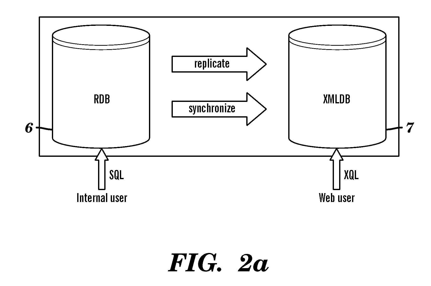
However, they cannot transform the whole relational database into an XML document nor synchronize a relational database into a replicate XML database.
Moreover, in such conventional systems and methods, the translation is without data semantics constraints considerations, and thus these methods may not be sufficient for an information highway on the web.
However, there are several disadvantages of this approach, one of them is that it is difficult to identify relationships among attributes of two schemas and to identity relationships among entity types and relationship types.
However, this approach requires users to learn another language and users may find it difficult to understand each individual database schema.
However, the data retrieved are actually stored in tables in the relational database and are not stored in an XML database.
A drawback of this approach is that the decomposition of a document produces a lot of tuples to be inserted into the database.
Therefore, the load time may increase for a large document.
One drawback of the Xparent system is that it requires a large number of joins to check edge-connections for processing complex queries.
A drawback of the X-Database system is that in this system the XML-Schema may be defined once in the beginning of the process and cannot be changed, but, in reality, the schema is changed over time in the majority of applications.

Method used


Image

  • System and method of translating a relational database into an XML document and vice versa
  • System and method of translating a relational database into an XML document and vice versa
  • System and method of translating a relational database into an XML document and vice versa

Examples


case study 1

[0273]This case study is of a Hospital Database System. An EER of the system is shown in FIG. 14. In this system, a patient 582 may have many record folders 584. Each record folder 584 may contain many different medical records 586 of the patient. The AE record 604, a ward record 606 and an outpatient record 608 may be generalised as a medical record 586. A country 588 has many patients 582. A borrower 596 of the record folder 584 of the patient 582 may be a department 612, a doctor 614 or another hospital 616 for their references or checking. Once a record folder 584 is borrowed, a loan history 598 may be created to record the details about it. The relational schemas for this case study are shown in Tables 13 to 25 below.

[0274]In the following, underlined and italic means primary key and * means foreign key.

TABLE 13CountryCountry NoCountry—NameC0001ChinaC0002CanadaC0003Korea

TABLE 14Record FolderFolder NoLocation*HKIDF_21Hong KongE3766849F_22KowloonE8018229F_23New TerritoriesE607788...

case study 2

[0295]This case study is for a bank loan application. In this study, a loan with an identity number belongs to a customer who has a customer identity number Customers have mortgage loans secured by loan securities. Each loan interest type may be accrued by multiple interest types. Each interest type may be assigned to different loans. Customers open accounts at different branches with a maturity date. Each loan is charged with interest of a rate of an interest type. All of these may be described in an extended entity relationship model such as that shown in FIG. 17.

[0296]Starting from the entity Loan 672 in the EER model of FIG. 17, the relevant entities for it are determined. The relevant entities include the related entities that are navigable from the parent entity 672 in various relationships. The entity Customer 670 is in a many-to-many relationship 674 defined as secured with the parent entity 672. The entity Security 676 is in a many-to-many relationship 674 defined as secure...


PUM


Abstract

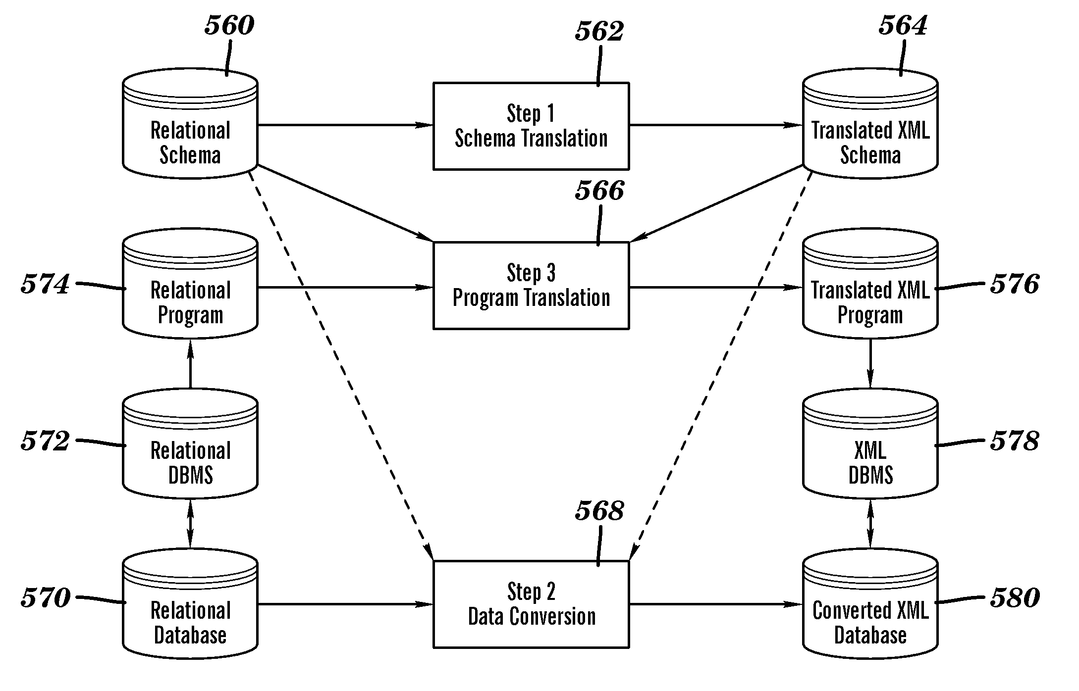
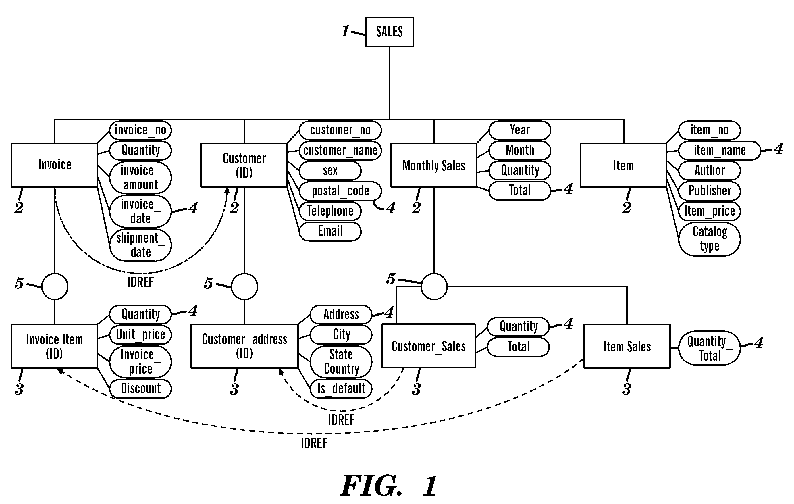
A method of translating a relational database into an XML document comprises generating an Extended Entity Relationship model from relational schema associated with the relational database and applying a schema translation process to the Extended Entity Relationship model to map the relational schema into a Document Type Definition (DTD) of an XML schema. An XML Tree Model is then generated from the Document Type Definition, the XML Tree Model being representative of one or more data semantics of the relational schema which are preserved as one or more data semantics in the XML document. Relational data from the relational database is then converted into the XML document using the relational schema and the XML schema from the Document Type Definition and / or the XML Tree Model. There is also described a method of translating an XML database into a relational database which comprises the reversal of the steps of the aforementioned method, and a system for implementing both methods.

Description

FIELD OF INVENTION[0001]The present invention relates to a method of translating a relational database into an XML document, a method of translating an XML database into a relational database, a method of data transmission of relational data through an XML document between a sender and a receiver over a network, a computer program, computer program product, a system of translating a relational database into an XML document and a system of translating an XML database into a relational database.BACKGROUND OF INVENTION[0002]Internet applications today are faced with the problem of replicating, transforming, exporting, or saving data from one format to another. This process may be laborious, tedious and error prone. The Internet holds within it the potential for integrating all information into a global network, promising access to information any time and anywhere. However, this potential has yet to be realised. At present, the Internet is merely an access medium. To realize the Intern...

Claims


Application Information

Patent Timeline
Patent Type & Authority Applications(United States)
IPC IPC(8): G06F17/30
CPCG06F17/2264G06F40/151
Inventor FONG, JOSEPH S. P.
Owner FONG JOSEPH S P
Learn More