
Air supply temperature control method of variable air quantity air conditioning system

A technology of air supply temperature and air conditioning system, which is applied in heating and ventilation control systems, heating and ventilation safety systems, heating methods, etc., and can solve the problems of inability to meet the high-precision requirements of system intelligent operation, unclear system control goals, and unfavorable self-control programming and implementation issues to achieve the effect of reliable and stable control and clear control objectives

Inactive Publication Date: 2013-04-17
杭州市城市建设科学研究院 +1
View PDF2 Cites 15 Cited by
  • Summary
  • Abstract
  • Description
  • Claims
  • Application Information

AI Technical Summary

Problems solved by technology

[0004] At present, there are many methods for resetting the air supply temperature commonly used: such as manual setting, manual setting according to weather and other factors, but this method is relatively random and relies too much on the experience and experience of the operator. Skills cannot meet the requirements of intelligent operation of the system; such as automatic setting according to outdoor parameters, automatic control system such as increasing or decreasing the set temperature according to outdoor meteorological parameters, etc., but this method has great limitations and cannot meet the requirements of system intelligence High-precision operation requirements; if the air supply temperature is adjusted according to the voting method, it is scientific, but the system control target is not clear, which is not conducive to automatic control programming and implementation

Method used


Image

  • Air supply temperature control method of variable air quantity air conditioning system
  • Air supply temperature control method of variable air quantity air conditioning system

Examples


Embodiment Construction

[0014] The present invention will be further described below with reference to the drawings and implementation methods.

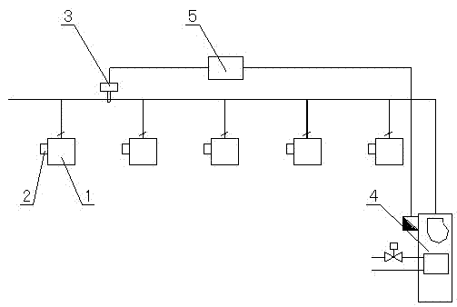
[0015] Such as figure 1 As shown, the present invention is composed of an air conditioning unit 4 with a fan inverter and an electric water valve, multiple variable air volume terminal devices (VAV) 1, a supply air temperature sensor and a supply air static pressure sensor 3, and a system controller 5. , Each variable air volume terminal device (VAV) 1 is equipped with its own variable air volume terminal device (VAV) controller 2.

[0016] The control method of the present invention is:

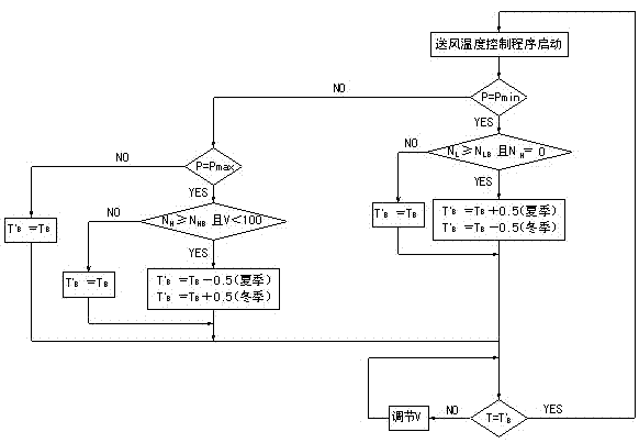
[0017] Such as figure 2 As shown, after the supply air temperature control program of the variable air volume air conditioning system is started, the controller collects the normal working quantity of the terminal in real time N 0 , The maximum number of valve positions at the end N H , The minimum number of valve positions at the end N L , Air supply temperature T, air duct s...


PUM


Abstract

The invention discloses an air supply temperature control method of a variable air quantity air conditioning system. The method includes adjusting a motor-driven water valve of an air conditioning unit by comparison of actual measured air supply temperature and set air supply temperature to ensure that the air supply temperature is stabilized at the set value, setting the air supply temperature and conducting automatic resetting combined with air pipe static pressure and tail end valve position. When the air pipe static pressure reaches the lowest value under work conditions in summer, the tail end largest valve position number is larger than the set value and openness of the motor-driven valve is smaller than 100%, the set air supply temperature is reduced. Current set air supply temperature is maintained under other work conditions. The air supply temperature resetting model is opposite under work conditions in winter. The air supply temperature control method is clear in target and stable in control, is combined with the air pipe static pressure and the tail end valve position condition and achieves the aims of saving energy and running comfortably by resetting the set air supply temperature after the air pipe static pressure reaches the extreme value.

Description

Technical field [0001] The invention relates to a supply air temperature control method, in particular to a supply air temperature control method of a variable air volume air conditioning system. Background technique [0002] Variable air volume air conditioning system is an all-air air conditioning system with fixed air supply temperature and variable air volume to meet indoor load changes. The system has good energy-saving and comfort, meets the good requirements of users for indoor air quality, and is widely used in various buildings such as office buildings, hospitals, libraries and gymnasiums. [0003] Generally speaking, when the air conditioning load changes, the air supply temperature of the air conditioning unit is fixed in a variable air volume air conditioning system. Instead, the air supply volume is changed to meet the load change demand and energy-saving operation is realized through the fan frequency conversion. However, if a fixed supply air temperature is used dur...

Claims


Application Information

Patent Timeline
IPC IPC(8): F24F11/00
Inventor 应晓儿储雪松张劲松叶水泉
Owner 杭州市城市建设科学研究院
Learn More