
Method for controlling structural acoustic transmission on basis of combined type vibration isolation device

A compound, sound control technology, applied in the direction of vibration suppression adjustment, non-rotational vibration suppression, shock absorber, etc., can solve the problem of unsatisfactory vibration isolation effect, achieve high vibration isolation efficiency, isolate structural sound transmission, and reduce energy The effect of passing

Active Publication Date: 2013-04-17
STATE GRID CORP OF CHINA +2
View PDF4 Cites 19 Cited by
  • Summary
  • Abstract
  • Description
  • Claims
  • Application Information

AI Technical Summary

Problems solved by technology

A large number of studies have pointed out that the existing simple vibration isolation devices are only very effective for isolation in the low frequency domain, but for high frequency vibration interference above 100 Hz, the vibration isolation effect is not ideal

Method used


Image

  • Method for controlling structural acoustic transmission on basis of combined type vibration isolation device
  • Method for controlling structural acoustic transmission on basis of combined type vibration isolation device
  • Method for controlling structural acoustic transmission on basis of combined type vibration isolation device

Examples


Embodiment Construction

[0048] The preferred embodiments of the present invention will be described in detail below in conjunction with the accompanying drawings; it should be understood that the preferred embodiments are only for illustrating the present invention, rather than limiting the protection scope of the present invention.

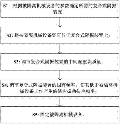
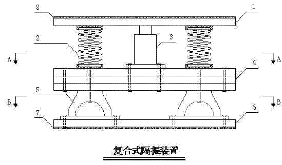
[0049] figure 1 It is a flow chart of a preferred embodiment of the present invention, figure 2 It is a schematic diagram of a composite vibration isolation device in a preferred embodiment of the present invention, wherein the composite vibration isolation device includes a top layer of structural rubber 8, a bearing panel 1, a spring vibration isolator 2, a damper 3, an intermediate mass 4, and a rubber vibration isolator 5. Base panel 6, underlying structure rubber 7; the rubber vibration isolator 5 is installed on the base panel 6, and the intermediate mass 4 is installed on the rubber vibration isolator 5; the spring vibration isolator 2 and the damper 3 is insta...


PUM


Abstract

The invention discloses a method for controlling structural acoustic transmission on the basis of a combined type vibration isolation device. The method includes steps of S1, determining the required combined type vibration isolation device according to parameters of isolated mechanical equipment; S2, vertically placing the isolated mechanical equipment on the combined type vibration isolation device; S3, adjusting the weight of a middle counterweight of the combined type vibration isolation device; S4, adjusting the natural frequency of the combined type vibration isolation device so that the natural frequency of the combined type vibration isolation device is lower than the structural vibration acoustic transmission frequency generated during operation of the isolated mechanical equipment; and S5, fixing the isolated mechanical equipment. The method has the advantages that propagation of noise of high-frequency structure is controlled by a combined type vibration isolation system, the vibration isolation device is arranged between the isolated mechanical equipment and a carrying foundation, performance parameters of upper and lower vibration isolators, a damper and the middle counterweight are matched with one another, the middle counterweight absorbs energy, and the spring and rubber isolators effectively isolate vibration, so that energy transmission of the structural noise is reduced, and the structural acoustic transmission of mechanical vibrating equipment is efficiently isolated.

Description

technical field [0001] The invention relates to the field of vibration control, in particular to a structural sound transmission control method of a composite vibration isolation device. Background technique [0002] The noise in the power distribution room is mainly electromagnetic noise and mechanical noise generated during the operation of the transformer. The electromagnetic noise is mainly caused by the magnetostriction of the silicon steel sheet and the electromagnetic force in the winding, and the mechanical noise is caused by the vibration of the equipment and the operation of the cooling fan. Most of the transformers used in the distribution room of the community are dry-type transformers. Research results at home and abroad show that the noise of dry-type distribution transformers is mainly caused by the magnetostriction of the iron core. Since the change cycle of magnetostriction is exactly the half cycle of the power supply frequency (the basic frequency of powe...

Claims


Application Information

Patent Timeline
Patent Type & Authority Applications(China)
IPC IPC(8): F16F13/04
CPCF16F15/02F16F15/022
Inventor 徐禄文高芳清范晨光孙春平张松涵邹岸新
Owner STATE GRID CORP OF CHINA
Learn More