
10MW-rank seat stand type wind guider turbine power generator system

A technology for turbine generators and wind turbines, applied in the mechanical and electrical fields, can solve the problems of difficulty in meeting the power of a single machine, increase in manufacturing costs, and low structural strength of cantilever beams, so as to reduce weight and cost, reduce manufacturing difficulty and cost, and reduce installation costs. The effect of easy maintenance

Inactive Publication Date: 2013-04-17
SHANGHAI WIND NEW ENERGY TECH
View PDF1 Cites 6 Cited by
  • Summary
  • Abstract
  • Description
  • Claims
  • Application Information

AI Technical Summary

Problems solved by technology

In order to increase the wind interception area, the length of the blade is also increasing on the basis of the advancement of material technology and manufacturing technology. However, due to the low structural strength of the cantilever beam of the blade, some data show that in super-large turbines, with the increase of blade length , the rated power increases with a quadratic function, but the manufacturing cost increases with a cubic relationship. Therefore, the improvement of the stand-alone power is limited by the economical and technical aspects of the blades. The transformation will also be limited by other wind power supporting components, such as the increase in volume and weight of generators, and systemic problems such as towers, pitch and wind yaw are also becoming more and more prominent, and breakthroughs in turbine technology solutions are still awaited

Method used


Image

  • 10MW-rank seat stand type wind guider turbine power generator system
  • 10MW-rank seat stand type wind guider turbine power generator system
  • 10MW-rank seat stand type wind guider turbine power generator system

Examples


Embodiment Construction

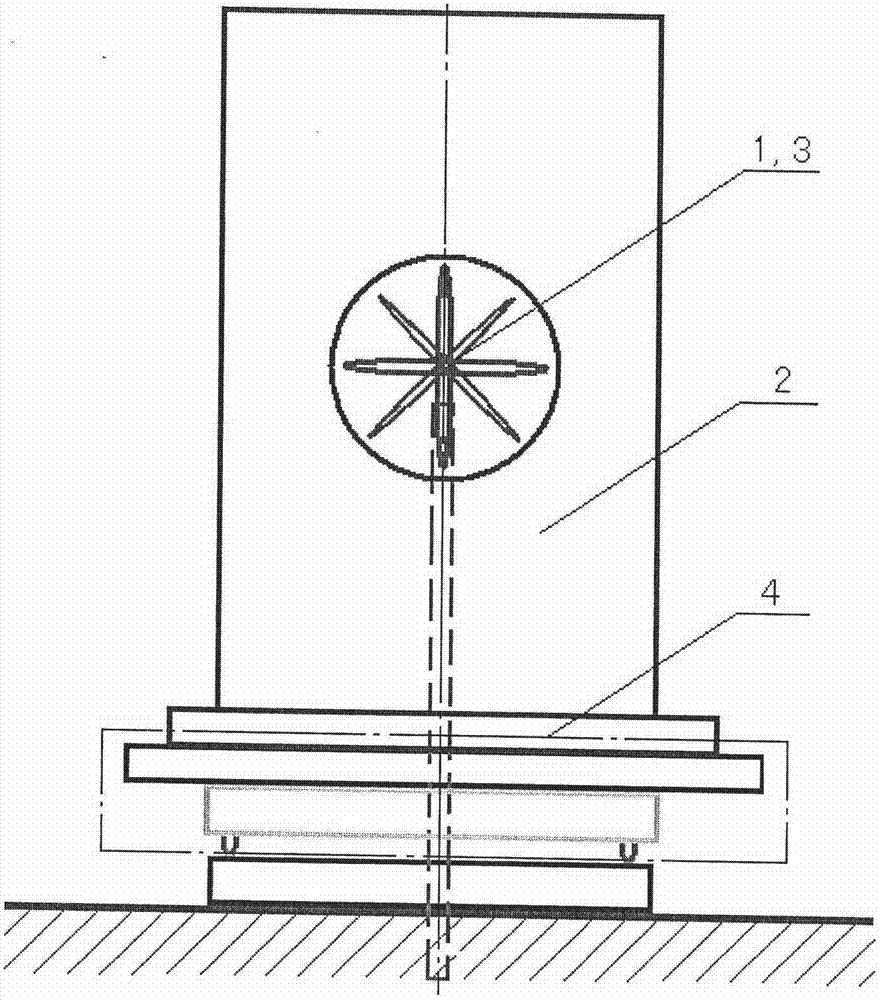
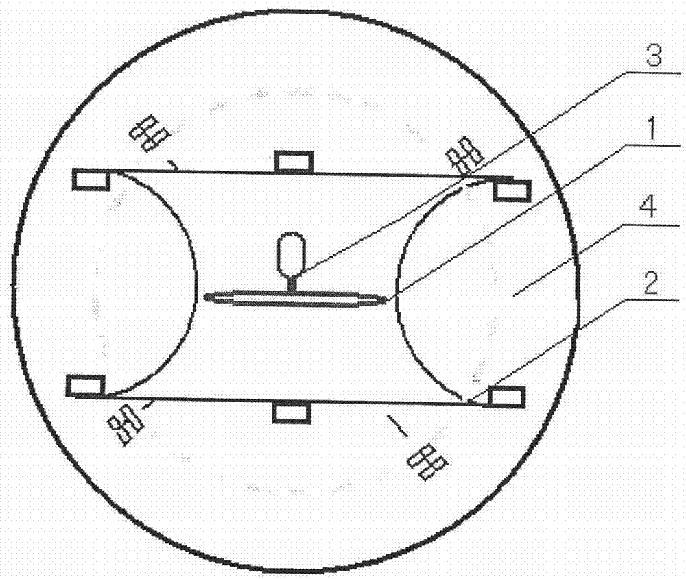
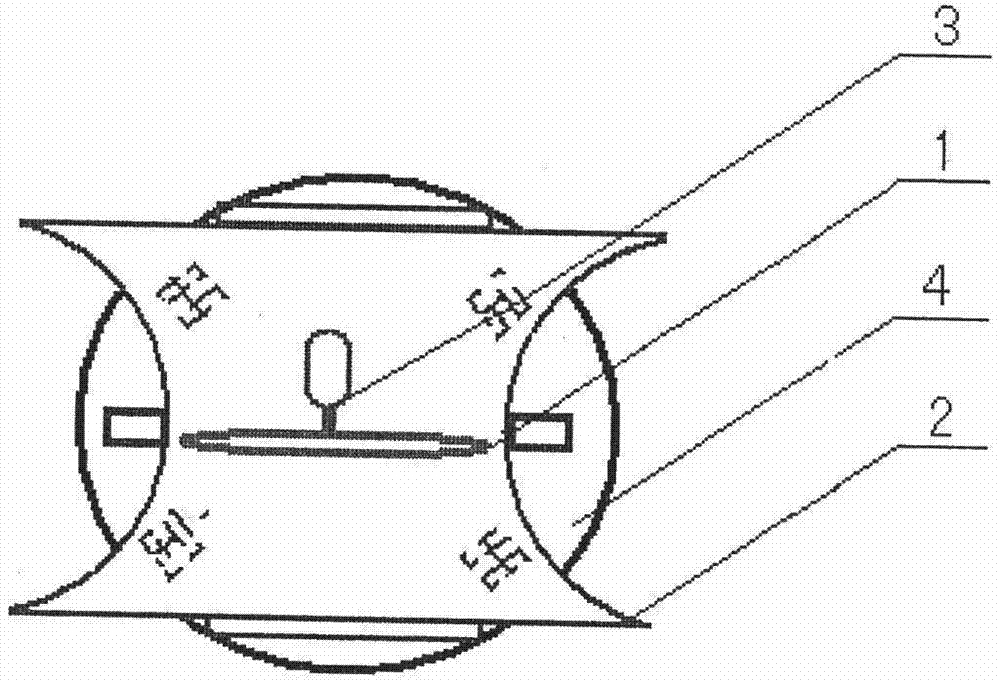
[0012] figure 1 It is a schematic plan view of the platform wind turbine system of the present invention. exist figure 1 Among them, the blades of the turbine (1) are located in the narrowest air channel in the middle of the air guide tank formed by the air guide body (2), and all the air flow entering the air guide body is guided to the center of the tank body, forming The concentrated kinetic energy with higher wind speed and higher density is blown to the turbine, so the blades of the turbine do not need to be as long and as few as the original three-blade, and can refer to the short-blade and multi-blade forms in steam turbines or gas turbines. Medium speed turbine blades, and single or multi-stage turbine blades. As a schematic, the six blades drawn in the figure are just a schematic scheme. The number, shape and stages of the specific blades of the turbine, including the design of the air guide body, should be based on the principle of air pillars, and the parameters o...


PUM


Abstract

A 10MW-rank seat stand type wind guider turbine power generator system is designed for industry requirement of upgrading a current wind power unit to that with higher single-machine capacity technology. By concentrating wind energy with a wind guide groove, increasing wind speed and adopting a medium and high-speed short-vane turbine to drive an alternating-current power generate to generate power, dependency on a gearbox is reduced, and more wind energy can be intercepted. Meanwhile, a tower and a variable-pitch blade device are omitted in a seat stand structure utilized as a groove carrier, power generation wind-speed range is enlarged, functions of the seat stand structure originally including a yawing function are increased to include yawing, wind regulating and auxiliary braking, and an implementing site is changed to the ground from overhead site, many technical difficulties caused by upsizing are solved by the new design, and power cost of unit loading is expected to reduce.

Description

field of invention [0001] The invention belongs to the technical field of machinery and electricity, and specifically proposes a platform-type wind power generation system device composed of a wind guide body turbine structure. Background technique [0002] A wind turbine is a new energy device that converts the kinetic energy of the wind into mechanical energy suitable for the rotation of the generator shaft, and drives the generator to rotate to generate electricity. Industrial practice has proved that in the horizontal axis turbines that are widely used at present, the increase in the power of a single machine is conducive to reducing The cost of installed capacity per unit power and the kWh cost of wind power generation. Therefore, the rated power capacity of a single machine continues to increase, and the single machine power of horizontal axis turbines has generally increased from the megawatt level at the end of the last century to the current 3-6 megawatt level. , an...

Claims


Application Information

Patent Timeline
Patent Type & Authority Applications(China)
IPC IPC(8): F03D9/00F03D11/00
CPCY02E10/72
Inventor 於岳亮於宙
Owner SHANGHAI WIND NEW ENERGY TECH
Learn More