
Magnetic roller

A technology of rollers and magnetic force, applied in textiles and papermaking, drafting equipment, spinning machines, etc., can solve the problems of affecting processing efficiency, straining fibers, and poor processing effects, so as to improve stability, avoid wear, and prevent forced The effect of turning

Inactive Publication Date: 2013-04-17
SUZHOU ZHANHUA TEXTILE
View PDF7 Cites 0 Cited by
  • Summary
  • Abstract
  • Description
  • Claims
  • Application Information

AI Technical Summary

Problems solved by technology

[0003] The roller has high requirements on the driving force. If the roller rotates too fast or the torque is too large, the fiber will be strained. If the roller rotates too slowly or the torque is too small, the processing effect will be poor and the processing efficiency will be affected.

Method used


Image

  • Magnetic roller
  • Magnetic roller
  • Magnetic roller

Examples


Embodiment 1

[0024] refer to figure 1 , image 3 , the magnetic roller includes a roller 100, the two ends of the roller 100 are pivotally connected to the roller support, and the two ends of the roller 100 and the roller support corresponding to the two ends are provided with a magnetic clutch device.

[0025] refer to figure 1 , figure 2 with image 3 The magnetic clutch device is composed of a roller end face provided with a first permanent magnet 110 and a driving cake 200 with a second permanent magnet 210 coaxially arranged opposite to the roller end face, the first permanent magnet 110 and the The magnetic pole connection line of the second permanent magnet 210 is arranged parallel to the axis of the roller 100 , and the polarity direction of the first permanent magnet 110 is opposite to that of the second permanent magnet 210 .

[0026] For the magnetic roller mentioned above, the first permanent magnets 110 and the second permanent magnets 210 are evenly distributed on the en...

Embodiment 2

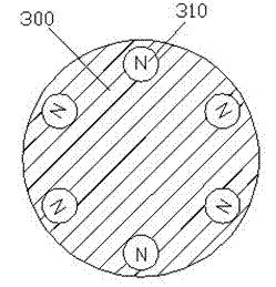
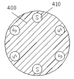
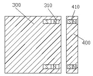
[0031] refer to Figure 4 , Image 6 , the magnetic roller includes a roller 300, the two ends of the roller 300 are pivotally connected to the roller support, and the two ends of the roller 300 and the roller support corresponding to the two ends are provided with a magnetic clutch device.

[0032] refer to Figure 4 , Figure 5 with Image 6 The magnetic clutch device is composed of a roller end face provided with a third permanent magnet 310 and a driving cake 400 with a fourth permanent magnet 410 coaxially arranged opposite to the roller end face, the third permanent magnet 310 and the The line connecting the magnetic poles of the fourth permanent magnet 410 is arranged perpendicular to the axis of the roller 300 , and the magnetic poles of the third permanent magnet 310 and the corresponding position of the fourth permanent magnet 410 are opposite.

[0033] For the magnetic roller mentioned above, the third permanent magnet 310 and the fourth permanent magnet 410 are...


PUM


Abstract

The invention provides a magnetic roller. The magnetic roller comprises a roller, wherein two ends of the roller are pivoted into a roller support; magnetic clutch devices are arranged at the two ends of the roller and in the roller support corresponding to the two ends; each magnetic clutch device is composed of a roller end face which is provided with a permanent magnet and a driving cake which is coaxially arranged in opposition to the roller end face, and provided with a permanent magnet; each magnetic pole connecting line of each two permanent magnets is arranged to be vertical to the axial line of the roller; and the magnetic poles at corresponding positions among the permanent magnets are opposite. By the adoption of the magnetic clutch devices which regard magnetism as a drive device of the roller, the roller when being overloaded can actively and temporarily disconnect to the drive source to prevent conveyed fibers from pulling damage caused by enforced rotation.

Description

technical field [0001] The invention relates to the field of textile machinery, in particular, a roller using a magnetic clutch device. Background technique [0002] Cylindrical rotating parts that play the roles of feeding, drafting, and output in textile machinery have the meaning of rollers and shafts. Widely used in drafting, carding, conveying and other mechanisms. According to the role played, it is divided into drafting roller, feeding roller, pressing roller, working roller and so on. The drafting roller is the main part of the drafting mechanism of the spinning machine. The upper roller and the lower roller are paired to form a roller nip, which holds the yarn for drafting. The quality of the rollers affects the uniformity of the output sliver. Most of the top rollers used in spinning machinery are covered with elastic materials, commonly known as top rollers. There are also smooth rollers, called iron rollers or lightweight rollers, and individual machines als...

Claims


Application Information

Patent Timeline
Patent Type & Authority Applications(China)
IPC IPC(8): D01H5/74
Inventor 欧阳文贻
Owner SUZHOU ZHANHUA TEXTILE
Learn More