Voltage regulator circuit

A voltage stabilizing circuit and voltage stabilizing tube technology, applied in the electronic field, can solve problems such as unfavorable stable operation of integrated circuit chips, misoperation, and insufficient stability of output terminal voltage

Inactive Publication Date: 2013-04-10
OCEANS KING LIGHTING SCI&TECH CO LTD +1
View PDF4 Cites 6 Cited by
  • Summary
  • Abstract
  • Description
  • Claims
  • Application Information

AI Technical Summary

Problems solved by technology

The output voltage of the traditional integrated circuit chip power supply circuit is not stable enough, and the ripple is large, which will cause the integrated circuit chip to work unstable and even malfun...

Method used


Image

  • Voltage regulator circuit

Examples


Embodiment Construction

[0010] In order to solve the problem of voltage instability, a voltage stabilizing circuit with better voltage stabilizing effect is proposed.

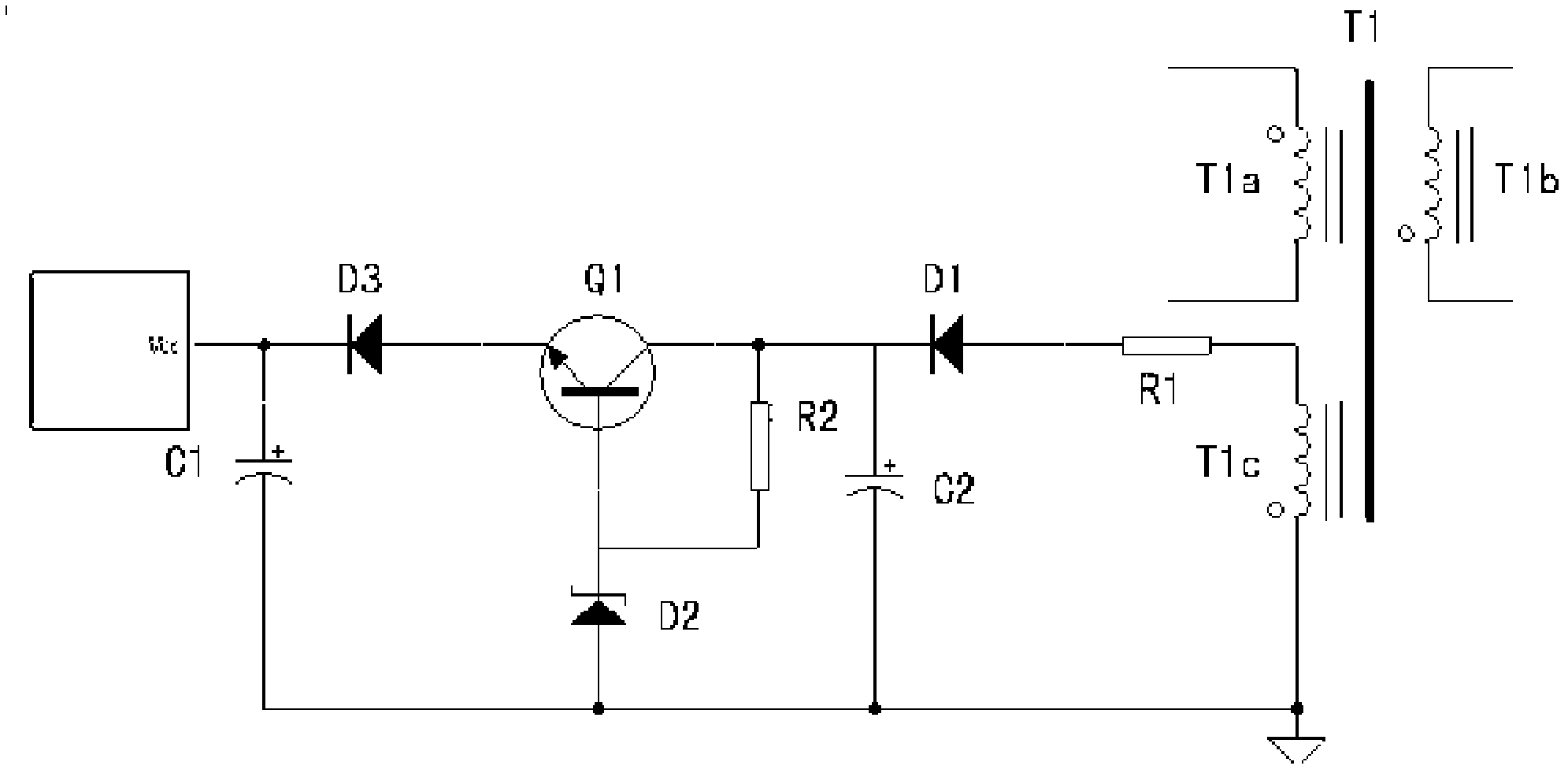
[0011] see figure 1 , which is a schematic diagram of a voltage stabilizing circuit according to an embodiment of the present invention, which includes a high frequency transformer T1, rectifier diodes D1 and D3, a voltage stabilizing tube D2, a triode Q1, resistors R1 and R2; capacitors C1 and C2. Wherein, the transformer T1 includes a primary winding T1a, a secondary winding T1b and an auxiliary winding T1c (that is, a power supply winding).

[0012] One end of the auxiliary winding T1c is grounded, the other end is connected to the anode of the diode D1 through the resistor R1, the cathode of the diode D1 is connected to the collector of the transistor Q1, the emitter of the transistor Q1 is connected to the anode of the diode D3, and the cathode of the diode D3 is connected to the regulator circuit output connection. The anode o...


PUM


Abstract

A voltage regulator circuit comprises a transformer T1, a diode D1 and a diode D3, a voltage-regulator tube D2, an audion Q1, a resistor R1 and a resistor R2, a capacitor C1and a capacitor C2. The transformer T1 comprises a primary winding T1a, a secondary winding T1b and an auxiliary winding T1c. One end of the auxiliary winding T1c is grounded and the other end is connected with the positive pole of the diode D1 through the resistor R1, the negative pole of the diode D1 is connected with the collector electrode of the audion Q1, the emitting electrode of the audion Q1 is connected with the positive pole of the diode D3, and the negative pole of the diode D3 is connected with the output end of the voltage regulator circuit. The positive pole of the capacitor C2 is connected with the negative pole of the diode D1, the negative pole of the capacitor C2 is connected with earth. The negative pole of the voltage-regulator tube D2 is connected with the base electrode of the audion Q1, the positive pole of the voltage-regulator tube D2 is grounded. The resistor R2 is connected in parallel between the collector electrode of the audion Q1 and the negative pole of the voltage-regulator tube D2. The positive pole of the capacitor C1 is connected with the negative pole of the diode D3, the negative pole of the capacitor C1 is grounded. The voltage regulator circuit can output more smooth voltage signals.

Description

【Technical field】 [0001] The invention relates to the field of electronic technology, in particular to a voltage stabilizing circuit for stabilizing voltage. 【Background technique】 [0002] In electronic products, the stability of the power supply system determines whether the entire electronic product works normally. Most of the current electronic products are equipped with an integrated circuit chip (IC) and a power supply circuit for supplying power to the integrated circuit chip. [0003] In the traditional integrated circuit chip power supply circuit, the current-limiting resistor and diode are used for rectification, and then an electrolytic capacitor is set for filtering to further smooth the rectified signal. [0004] Generally speaking, for integrated circuit chips to work normally and stably, the power supply voltage must be stable, and no useless interference signals appear. The output voltage of the traditional integrated circuit chip power supply circuit is no...

Claims


Application Information

Patent Timeline
IPC IPC(8): H02M5/10
Inventor 周明杰邵贤辉
Owner OCEANS KING LIGHTING SCI&TECH CO LTD
Why Eureka
Try Eureka