
Heat dissipation device applied to middle and high voltage inverter

A technology of medium and high voltage frequency converters and heat sinks, which is applied in the direction of output power conversion devices, electric solid state devices, semiconductor devices, etc., and can solve problems such as adverse effects on power device performance and life, increased electrical connection distance, and increased leakage inductance , to achieve the effect of shortening the electrical connection distance, reducing interference and reducing leakage inductance

Inactive Publication Date: 2013-04-10
DELTA ELECTRONICS (SHANGHAI) CO LTD
View PDF5 Cites 11 Cited by
  • Summary
  • Abstract
  • Description
  • Claims
  • Application Information

AI Technical Summary

Problems solved by technology

On the other hand, the large distance between power devices will increase the electrical connection distance, resulting in increased leakage inductance and low efficiency, which will also adversely affect the performance and life of power devices

Method used


Image

  • Heat dissipation device applied to middle and high voltage inverter
  • Heat dissipation device applied to middle and high voltage inverter
  • Heat dissipation device applied to middle and high voltage inverter

Examples


Embodiment Construction

[0031] In order to make the technical content disclosed in this application more detailed and complete, reference may be made to the accompanying drawings and the following various specific embodiments of the present invention, wherein the same symbols in the accompanying drawings represent the same or similar components. However, those of ordinary skill in the art should understand that the embodiments provided below are not intended to limit the scope covered by the present invention. Furthermore, the drawings are for schematic illustration only and are not drawn to their full scale.

[0032] The specific embodiments of various aspects of the present invention will be described in further detail below with reference to the accompanying drawings.

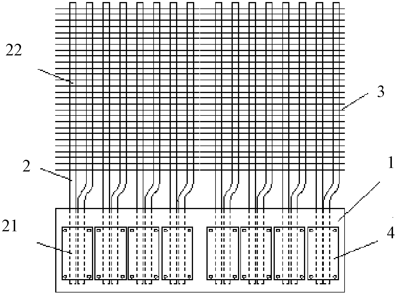
[0033] figure 1 A front view showing a preferred embodiment of the cooling device for medium and high voltage frequency converters according to the present invention. refer to figure 1 , a heat dissipation device suitable for he...


PUM


Abstract

The invention provides a heat dissipation device which is suitable for carrying out heat dissipation on a plurality of heating elements in a middle and high voltage inverter. The heat dissipation device comprises a heat dissipation substrate, at least a set of heat pipes and a plurality of cooling fins, wherein at least one surface of a first surface and a second surface of the heat dissipation substrate is provided with the heating elements, and the set of heat pipes comprise a plurality of heat pipes. Each heat pipe comprises an evaporation segment and a condensation segment, and the evaporation segment is buried in an inner layer of the heat dissipation substrate to absorb heat from the heating elements. The plurality of cooling fins are arranged to be intersected with the heat pipes and fixedly connected with the condensation segments of the heat pipes, and therefore heat released by the condensation segments is transferred to the air. Moreover, contact portions between the set of heat pipes and the plurality of cooling fins are arranged in a triangle and intercrossing mode. A plurality of power devices in the inverter are placed on at least one surface of the heat dissipation substrate, and a plurality of sets of heat pipes are buried in the inner layer of the heat dissipation substrate. Moreover, the contact portions between the set of heat pipes and the plurality of cooling fins are arranged in a triangle and intercrossing mode so that heat dissipation efficiency of each power device can be effectively improved.

Description

technical field [0001] The invention relates to a heat dissipation device, in particular to a heat dissipation device for medium and high voltage frequency converters. Background technique [0002] At present, in many power electronic circuits, the application of medium and high voltage frequency converters is more and more extensive. It is a power control device that uses the turn-on and turn-off of semiconductor power devices to change the frequency. speed, changing power factor, overcurrent / overvoltage / overload protection and other functions. However, when these power devices are frequently switched between on and off, high heat energy is often generated, so it is necessary to set up a corresponding radiator to effectively dissipate the power devices, thereby ensuring the normal operation of the medium and high voltage inverter. [0003] Generally speaking, radiators mainly include: flat radiators, parallel rib radiators and interdigitated radiators, among which flat rad...

Claims


Application Information

Patent Timeline
Patent Type & Authority Applications(China)
IPC IPC(8): H02M1/00H05K7/20
CPCH01L23/427F28D15/0275H01L2924/0002H01L2924/00
Inventor 仝爱星甘鸿坚
Owner DELTA ELECTRONICS (SHANGHAI) CO LTD
Learn More