
Multi-narrow-pulse laser light source and achieving method thereof

A laser light source, narrow pulse technology, applied in lasers, laser parts, semiconductor lasers, etc., can solve problems such as the inability to meet long-distance measurement applications, and achieve the effect of solving the contradiction between power increase and nonlinearity

Inactive Publication Date: 2013-04-10
SHANGHAI BOOM FIBER SENSING TECH
View PDF0 Cites 3 Cited by
  • Summary
  • Abstract
  • Description
  • Claims
  • Application Information

AI Technical Summary

Problems solved by technology

However, the DTS system based on this single narrow pulse laser source can only meet the measurement requirements of short and medium distances, and cannot meet the long-distance measurement applications

Method used


Image

  • Multi-narrow-pulse laser light source and achieving method thereof
  • Multi-narrow-pulse laser light source and achieving method thereof
  • Multi-narrow-pulse laser light source and achieving method thereof

Examples


Embodiment 1

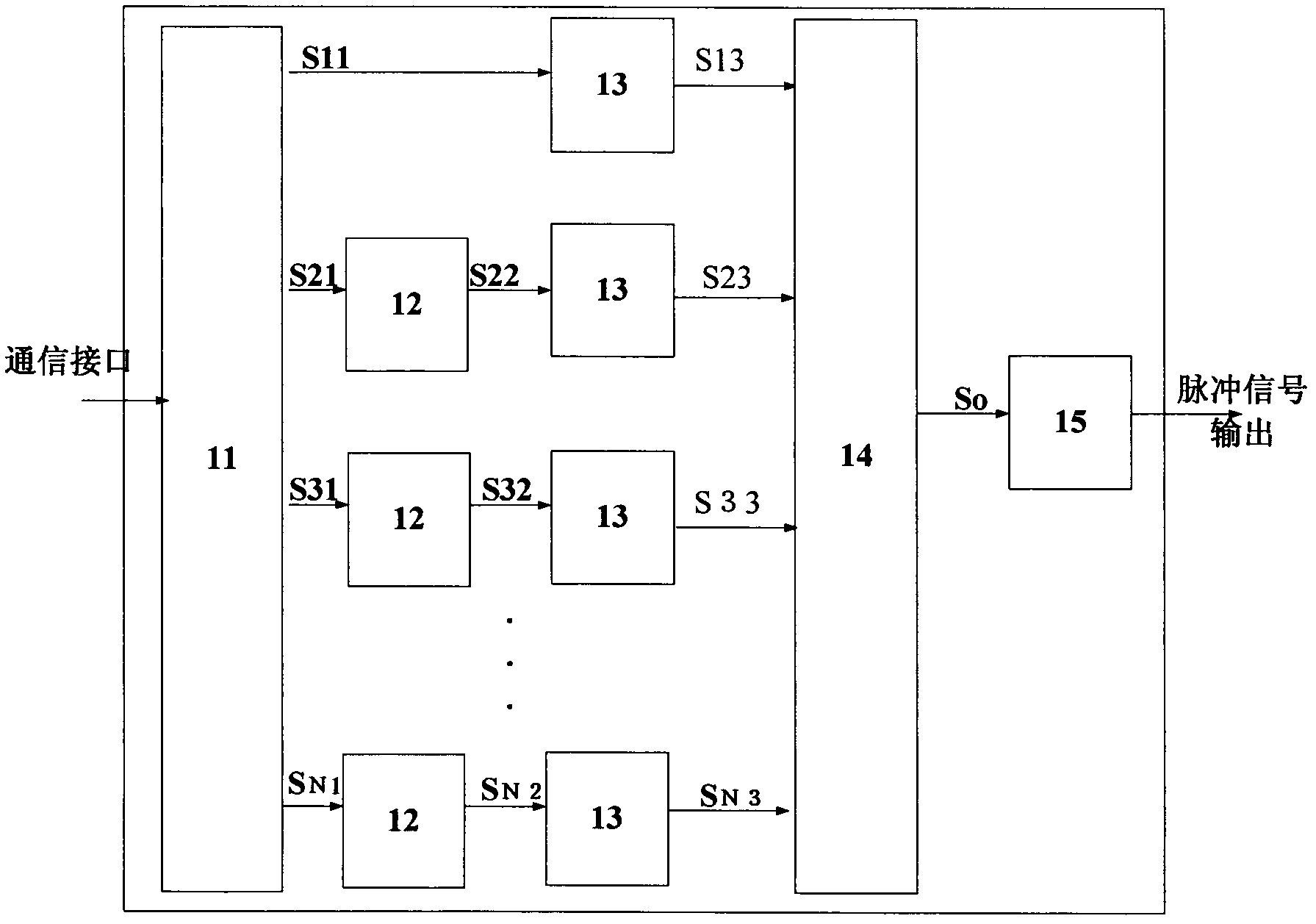
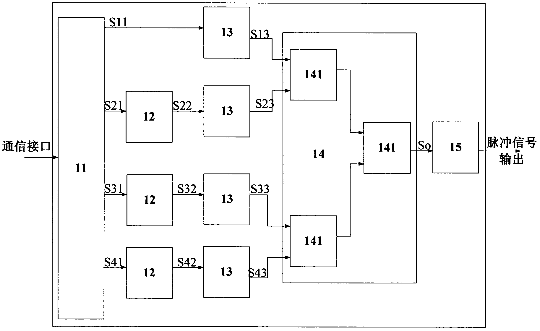
[0060] Example 1: Such as figure 1 , image 3 with Figure 4 Shown: Take N=4, the first output terminal of FPGA11 is connected to the input terminal of the first PWM generator 13, the other output terminals of FPGA11 are respectively connected to the input terminals of three delay line devices 12, three delay lines The output terminals of the device 12 are respectively connected to the input terminals of the second, third, and four PWM generators 13, and the output terminals of the four PWM generators 13 are respectively connected to the four input terminals of the multi-channel high-speed or logic block 14 one by one. The output end of the high-speed OR logic block 14 is connected to the line drive device 15.

[0061] Such as image 3 , Figure 4 Shown: Assume that the width of a narrow pulse of the narrow pulse signal So output by the narrow pulse signal generator 1 is T, the model of the PWM generator 13 is DS1023S, and the four trigger signals output by FPGA11 are: S11, S21,...


PUM


Abstract

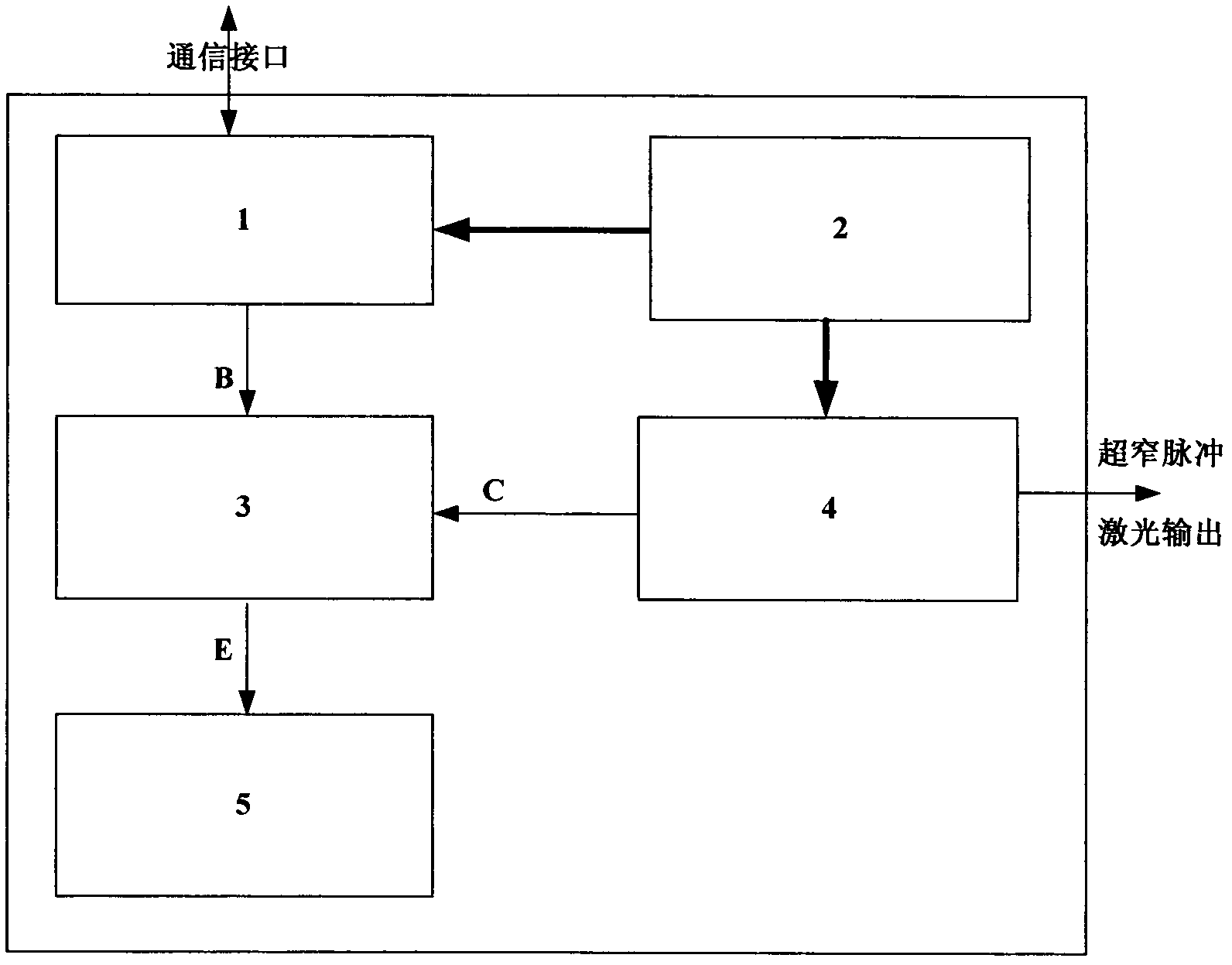
The invention discloses a multi-narrow-pulse laser light source and an achieving method thereof. The laser light source comprises a multi-narrow-pulse signal generator, a power source system, an avalanche transistor, a laser diode and an adjustable potentiometer, wherein an output end of the power source system is connected with an input end of the multi-narrow-pulse signal generator, and the other output end of the power source system is connected with an input end of the laser diode; an input end C of the avalanche transistor is connected with an output end of the laser diode, the other output end B is connected with an output end of the multi-narrow-pulse signal generator, and an output end E of the avalanche transistor is connected with the adjustable potentiometer. The multi-narrow-pulse laser light source has the advantages that multi-narrow-pulse signals generated by the multi-narrow-pulse signal generator are used for controlling connection and disconnection of the avalanche transistor, so that the laser diode driven by the avalanche transistor can generate multi-narrow-pulse laser having the same repeating frequency and pulse width with the multi-narrow-pulse signals; and a data transformation service (DTS) system based on the multi-narrow-pulse laser light source can overcome the contradiction of power increase and nonlinearity of the DTS system during temperature measuring, and the aim of long distance measuring can be achieved.

Description

Technical field [0001] The invention relates to the technical field of optical fiber temperature measurement, in particular to narrow pulse laser light source technology in the technical field of optical fiber temperature measurement. Background technique [0002] Distributed optical fiber temperature measurement system (hereinafter referred to as DTS system) is a temperature measurement system based on OTDR and Raman scattering principles, and its temperature sensor is optical fiber. DTS system composition generally includes high-power pulsed laser light source, optical fiber wavelength division multiplexing coupler, sensor optical cable, photodetector, signal amplification module, data acquisition module and system host (PC or industrial computer). The DTS system has been researched and developed for many years. At present, the system of medium and short distance (referring to the length of the measurable distance) is very mature and has been put on the market in large numbers....

Claims


Application Information

Patent Timeline
IPC IPC(8): H01S5/042G01K11/32G01K11/324
Inventor 黄正
Owner SHANGHAI BOOM FIBER SENSING TECH
Learn More