
Multi-band antenna

A multi-frequency antenna and high-frequency technology is applied to antennas, devices that enable antennas to work in different bands at the same time, and the structural form of radiation elements. It can solve the problems of large appearance size and heavy weight of triple-frequency antennas, and achieve compact structure. The effect of small size and increased gain

Inactive Publication Date: 2013-04-10
SHENZHEN GRENTECH CO LTD
View PDF0 Cites 11 Cited by
  • Summary
  • Abstract
  • Description
  • Claims
  • Application Information

AI Technical Summary

Problems solved by technology

However, the traditional tri-band antenna is large in size and heavy in weight

Method used


Image

  • Multi-band antenna
  • Multi-band antenna
  • Multi-band antenna

Examples


Embodiment Construction

[0024] The invention relates to a multi-system antenna for a wireless communication system. In the following, the present invention will be described by taking a tri-band dual-polarized antenna as an example.

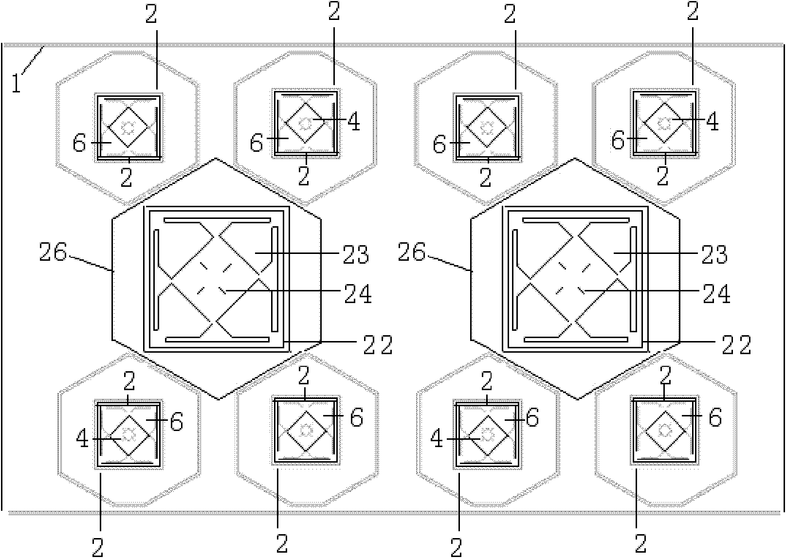
[0025] refer to figure 1 with figure 2 , the multi-frequency antenna includes a reflector 1 , several high-frequency oscillators and several low-frequency oscillators installed on the reflector 1 . Wherein, the low-frequency oscillators are arranged in two rows, and the high-frequency oscillators are arranged in a row and located between the two rows of low-frequency oscillators. A number of high-frequency isolation frames 25 and low-frequency isolation frames 26 are fixed to the reflector 1 for isolating corresponding high-frequency oscillators and low-frequency oscillators, respectively.

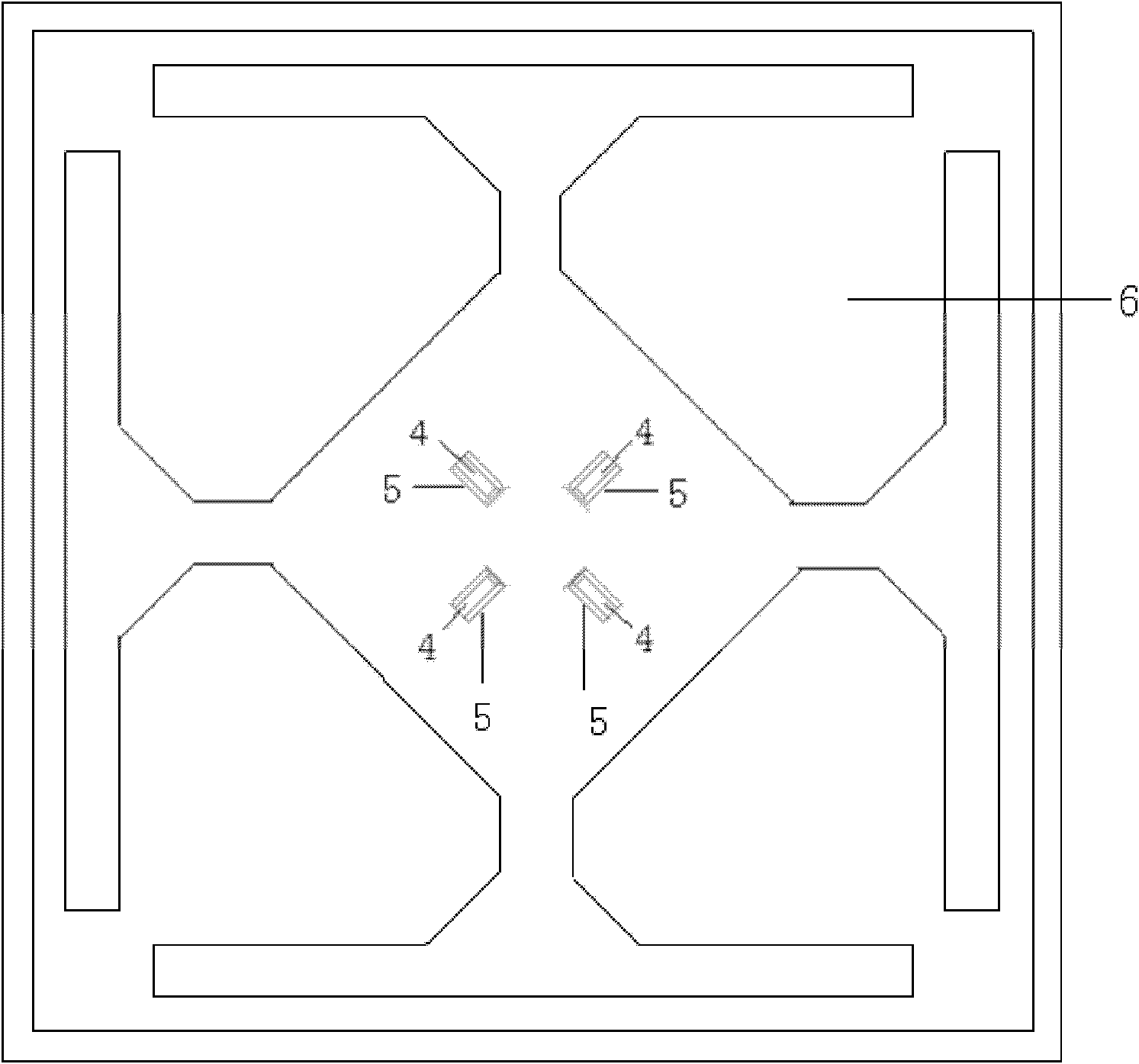
[0026] refer to Figure 3 to Figure 14 , the structure of the high-frequency oscillator and the low-frequency oscillator have a similar structure. Among them, the high-frequen...


PUM


Abstract

The invention relates to a multi-band antenna which is suitable for a wireless communication system. The multi-band antenna comprises a reflecting plate (1), a plurality of high frequency vibrators and a plurality of low frequency vibrators, wherein the plurality of high frequency vibrators and the plurality of low frequency vibrators are installed on the reflecting plate (1). The plurality of high frequency vibrators and the plurality of low frequency vibrators are arranged side by side. The multi-band antenna further comprises high frequency isolating frames (25) and low frequency isolating frames (26) which are fixed on the reflecting plate (1) and respectively used for isolating the high frequency vibrators and the low frequency vibrators. In a preferred scheme, the multi-band antenna is a triple-band antenna, the low frequency vibrators are arranged in two rows, and the high frequency vibrators are arranged in one row and located between the two rows of low frequency vibrators. The multi-band antenna is compact in structure and small in volume and has increased gain.

Description

【Technical field】 [0001] The invention relates to the field of antennas, in particular to a multi-frequency antenna of a mobile communication base station. 【Background technique】 [0002] Base station antenna feeder system is the most important component subsystem of wireless communication network. The growth of communication users and the expansion of communication traffic put forward new requirements for multi-system antennas with multi-operator common base stations. Currently, the tri-band antenna is the most commonly used multi-system antenna. However, the traditional tri-band antenna has a large appearance and a large weight. Therefore, an improved tri-band antenna is urgently needed. 【Content of invention】 [0003] It is an object of the present invention to provide a compact multi-frequency antenna. The multi-frequency antenna includes a reflector, several high-frequency vibrators and several low-frequency vibrators installed on the reflector, wherein: the plura...

Claims


Application Information

Patent Timeline
Patent Type & Authority Applications(China)
IPC IPC(8): H01Q1/38H01Q5/01H01Q5/10
Inventor 董政
Owner SHENZHEN GRENTECH CO LTD
Learn More