Multi-cylinder rotary compressor
A rotary compressor, multi-cylinder technology, applied in rotary piston/oscillating piston pump components, elastic fluid rotary piston/oscillating piston pump combinations, mechanical equipment, etc., can solve the reduction of piston efficiency , insufficient shaft rigidity, longer shaft length, etc., to achieve the effect of improving rigidity and vibration, improving wear failure and reducing compression efficiency
- Summary
- Abstract
- Description
- Claims
- Application Information
AI Technical Summary
Problems solved by technology
Method used
Image
Examples
Embodiment 1
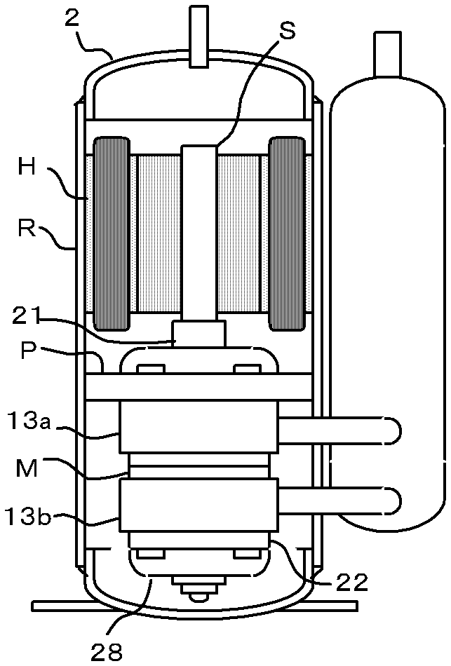
[0039] see figure 1 , which is the internal structure of the rotary compressor R. In the rotary compressor R, a compression mechanism P and a motor H are arranged in a hermetic casing, and these are fixed to the inner wall of the casing. The first cylinder 13a and the second cylinder 13b of the compression mechanism P are divided by the intermediate plate M.
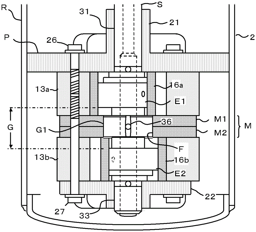
[0040] see figure 2 , is a detailed view of the compression mechanism P. In the first cylinder 13a and the second cylinder 13b constituting the compression mechanism P, a first piston 16a and a second piston 16b, and a sliding vane (not shown) that reciprocates in synchronization with the same are arranged. An intermediate plate M, consisting of a first plate M1 and a second plate M2, distinguishes these cylinders between the two cylinders.
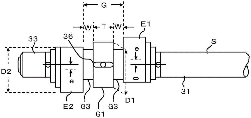
[0041] The connecting shaft G of the eccentric crankshaft S arranged at the center of the compression mechanism P is a shaft connecting the first eccentric shaft E1 and the sec...
Embodiment 2
[0053] see Figures 9-10 In this embodiment 2, a central groove 45 with an inner diameter of d2 is arranged in the center of the second flat plate M2, and a central hole 44 with an inner diameter of d1 is opened on the outer plane of the central groove 45.
[0054] In Embodiment 2, the inner diameter d3 of the center groove 45 is the inner diameter of the intermediate bearing F, so d2=d3. d2=d1+2e, a thin-walled thrust portion 46 is formed at the bottom of the central groove 45, see Figure 10 . As in Embodiment 1, d2=d3=D1+c. Also, d1=D2+c.
[0055] see Figure 11 , representing the process of inserting the second flat plate M2 into the eccentric crankshaft S to assemble the middle partition plate M. Same as Embodiment 1, when the second flat plate M2 moves upward through the outer circumference of the second eccentric shaft E2, it is as follows: Figure 11 . Furthermore, in order to ensure that the center of the center hole 44 is consistent with the center of the main...
Embodiment 3
[0061] see Figure 13 , this embodiment 3 is composed of one flat plate to form the middle partition plate M, so compared with the embodiment 1 or embodiment 2 in which the middle partition plate M is composed of two flat plates, the processing and assembly with the middle partition plate M are relatively easy The advantage, the disadvantage is that the width or bearing length of the intermediate bearing F will be halved. However, the condition of increasing the width W of the second intermediate shaft G3 is achievable. Furthermore, in Example 3, the outer diameter D1 of the first intermediate shaft G1 and the outer diameter D2 of the second eccentric shaft cannot be different. That is, D1≈D2.
[0062] The remaining unmentioned parts are shown in Example 1, and will not be repeated.
PUM
 Abstract
Description
Claims
Application Information
 - R&D Engineer
- R&D Manager
- IP Professional
- Industry Leading Data Capabilities
- Powerful AI technology
- Patent DNA Extraction
Browse by: Latest US Patents, China's latest patents, Technical Efficacy Thesaurus, Application Domain, Technology Topic, Popular Technical Reports.
© 2024 PatSnap. All rights reserved.Legal|Privacy policy|Modern Slavery Act Transparency Statement|Sitemap|About US| Contact US: help@patsnap.com


