
Correcting drill bit based on liquid support

A technology of liquid support and drill bit, which is applied in the direction of drill repair, drilling tool accessories, drilling/drilling equipment, etc., which can solve the problems of complex drilling process and achieve the effect of enhancing rigidity

Inactive Publication Date: 2013-04-10
JIANGSU UNIV
View PDF4 Cites 5 Cited by
  • Summary
  • Abstract
  • Description
  • Claims
  • Application Information

AI Technical Summary

Problems solved by technology

[0007] However, the above methods make the drilling process complicated, or need to add new and expensive detection equipment

Method used


Image

  • Correcting drill bit based on liquid support
  • Correcting drill bit based on liquid support
  • Correcting drill bit based on liquid support

Examples


Embodiment 1

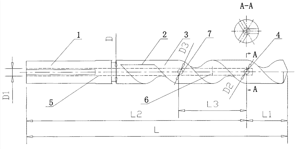
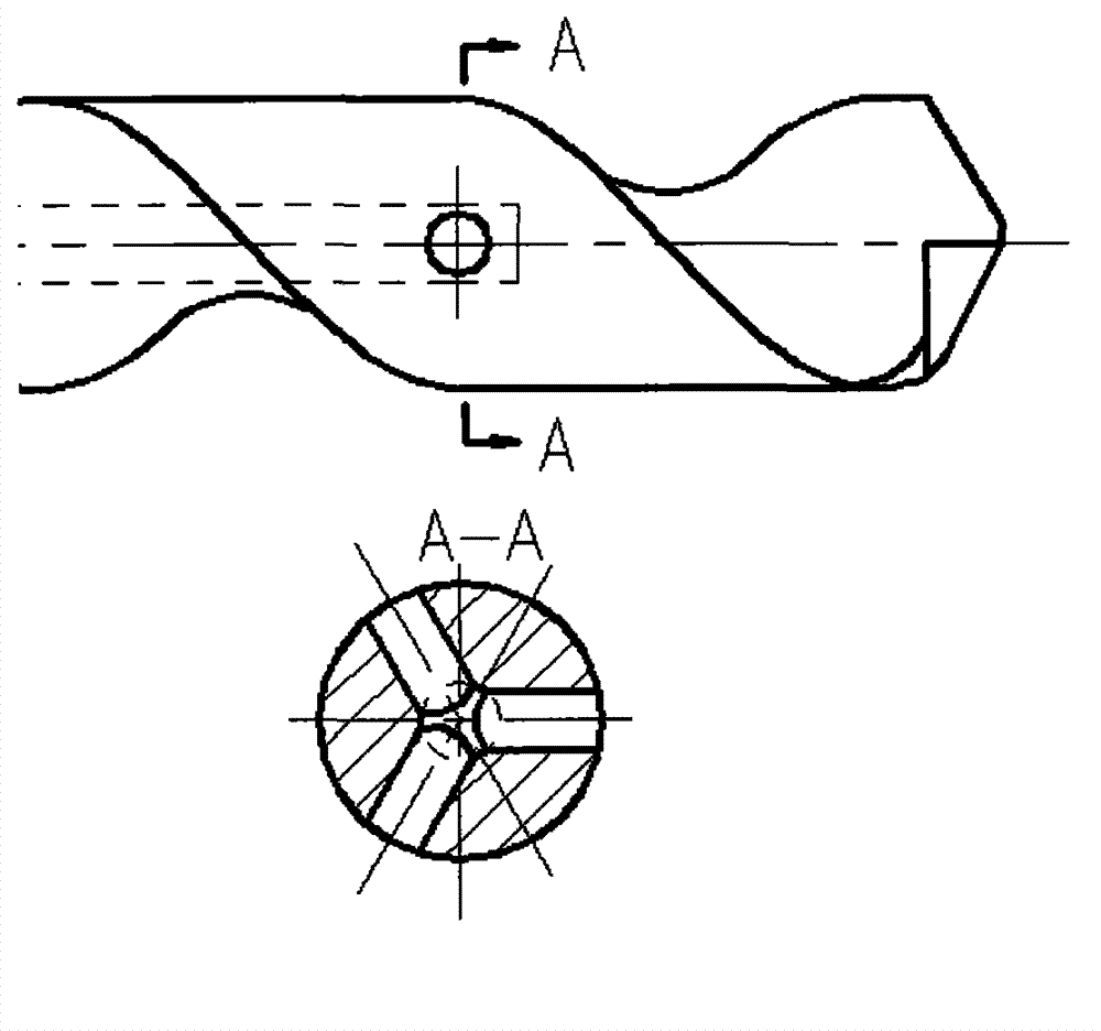
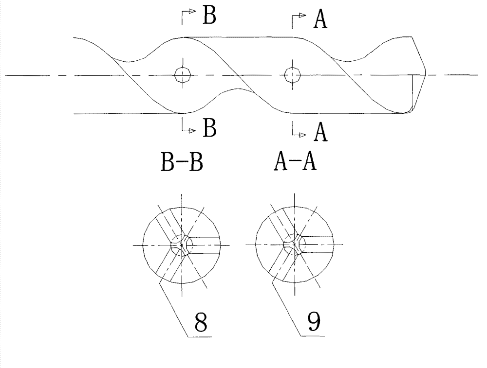
[0025] combined with figure 1 And attached figure 2 , a liquid-supported deviation-correcting drill bit, first drill a blind hole (5) through the coolant along the center line inside the drill bit, and drill the blind hole (5) through the coolant from the end of the drill shank (1), through The depth L2 of the blind hole (5) of the coolant is 80% to 90% of the total length L of the drill bit, and the diameter D1 of the blind hole (5) through the coolant is 10% to 15% of the diameter D of the drill bit. If D1 is greater than 1mm, then D1 is taken as 1 mm; on the cutting edge (3) of the drill blade (2), three evenly distributed microholes (4) are drilled radially evenly, and the axes of the three uniformly distributed microholes (4) are 120° to each other. Three evenly distributed micro-holes (4) are drilled to intersect with the blind hole (5) through which the coolant passes, and the distance L1 between the center of the three evenly distributed micro-holes (4) and the drill...

specific Embodiment approach

[0030] A deviation-correcting drill bit based on liquid support. First, a blind hole (5) through the coolant is drilled along the center line inside the drill bit. The blind hole (5) through the coolant is drilled from the end of the drill shank (1), and the coolant is passed through the hole. The depth L2 of the blind hole (5) of the liquid is 80% to 90% of the total length L of the drill bit, and the diameter D1 of the blind hole (5) through the coolant is 10% to 15% of the diameter D of the drill bit. If D1 is greater than 1mm, then D1 Take 1mm; on the cutting edge (3) of the drill blade (2), drill three evenly distributed microholes (4) in the radial direction, and the axes of the three uniformly distributed microholes (4) are 120° to each other, and the three A uniformly distributed microhole (4) is drilled to intersect with the blind hole (5) passing through the coolant, and the distance L1 between the center of the three uniformly distributed microholes (4) and the drill...


PUM


Abstract

The invention relates to the field of drilling machining and in particular relates to a correcting drill bit based on liquid support. A blind hole for passing through cooling liquid is drilled along the centre line in the drill bit; micro holes are uniformly distributed along the radial direction on a drill bit edge; axes of three uniformly-distributed micro holes mutually form an angle of 120 degrees, and penetrate through the blind hole for passing through the cooling liquid; during a drilling process, a drill shank is arranged on a machine tool; a pipeline of cutting fluid is connected with the blind hole for passing through the cooling liquid in a sealing manner; the cutting fluid is injected at a high speed from the blind hole for passing through the cooling liquid, ejected at a high speed from the three uniformly-distributed micro holes, and ejected to the inner wall of a small hole of the drill to form the liquid support, so that an phenomenon that the drill bit edge is eccentric due to internal defects of a processed workpiece during a drilling process is removed, and the centering of the drill bit edge is ensured, thereby ensuring the quality of all drill holes and achieving the effects of the cooling and lubricating at the same time. The correcting drill bit has the characteristics of a simple structure, convenience in operation and strong practicability.

Description

technical field [0001] The invention relates to the field of drilling processing, in particular to a liquid-supported deviation-correcting drill bit, which can eliminate the eccentric phenomenon of the drill edge due to internal defects of the processed object during the drilling process, and ensure the centering of the drill edge , At the same time play a cooling role, thereby ensuring the quality of the drilled hole. Background technique [0002] The drill bit is composed of a drill rod and a drill edge. During the drilling process, the eccentric phenomenon of the drill edge often occurs. This phenomenon is caused by manual operation. Another important reason is the internal defects of the processed material, such as the existence of hard spots and voids, that is, the inhomogeneity of the material. The eccentricity of the drill edge not only causes the eccentricity of the processed hole, which affects the processing quality, but also accelerates the wear of the drill edge...

Claims


Application Information

Patent Timeline
Patent Type & Authority Applications(China)
IPC IPC(8): B23B51/06
Inventor 王匀许桢英甘斐殷苏民王雪鹏范苏湘蒋素琴陈万荣
Owner JIANGSU UNIV
Learn More