Stamping die side punching waste discharging structure
A stamping die and side punching technology, which is applied in the field of waste discharge structure of stamping die side punching, can solve the problem of low failure probability and achieve the effects of low failure probability, simple structure, and high work safety and reliability
Inactive Publication Date: 2013-04-10
江苏振世达汽车模具有限公司
View PDF0 Cites 0 Cited by
- Summary
- Abstract
- Description
- Claims
- Application Information
AI Technical Summary
Problems solved by technology
[0005] The invention has simple structure, convenient processing and installation, low probability of failure in the working process, high working safety and reliability, convenient observation of waste discharge, and solves the shortcomings of traditional processing methods
Method used
View moreImage
Smart ImageViewing Examples

Examples
Embodiment Construction
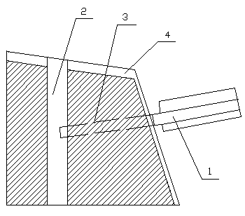
[0008] A punching die side punching waste discharge structure, including a die, a punch 1 and a forced discharger 2, the die includes a die insert 3 and a die sleeve 4, the die sleeve 4 is set Outside the die insert 3, the forced ejector 2 is arranged in the die insert 3, and the punch 1 is oblique to the die.
Login to View More PUM
 Abstract
The invention relates to a stamping die side punching waste discharging structure. The stamping die side punching waste discharging structure comprises a concave die, a plunger chip and a compelling material discharger. The concave die comprises a concave die plate insert and a concave die case, wherein the concave die case is arranged outside the concave die plate insert. The compelling material discharger is arranged inside the concave die plate insert. The plunger chip faces sideling towards the concave die. The stamping die side punching waste discharging structure is simple in structure, convenient to machine and install, low in failure probability in working process, high in working safe reliability, and capable of bringing convenience to the observation of the waste discharging condition and overcoming defects of a traditional treatment method.
Description
technical field [0001] The invention relates to a discharge device for punching waste in mechanical engineering, in particular to a discharge structure for punching waste on the side of a stamping die. Background technique [0002] Side punching molds must ensure that the waste can be discharged smoothly, especially in the production process of the automatic line, once the waste cannot be discharged smoothly, it will affect the production efficiency and may damage the mold. During the use of the mold, due to the blunt cutting edge and other reasons, there are burrs in the waste material, and the waste material forms a columnar shape, making it difficult to discharge. The traditional processing method installs a forced discharger in the mold structure, through which the discharge direction of the waste is changed, and the columnar waste is separated into a single piece or several pieces of waste, which can be discharged smoothly. However, this structure is difficult to proce...
Claims
Login to View More Application Information
Patent Timeline
 Patent Type & Authority Applications(China)
IPC IPC(8): B21D37/10B21D28/34B21D45/02
Inventor 焦惠泉
Owner 江苏振世达汽车模具有限公司
Features
- R&D
- Intellectual Property
- Life Sciences
- Materials
- Tech Scout
- Unparalleled Data Quality
- Higher Quality Content
- 60% Fewer Hallucinations
Learn More Browse by: Latest US Patents, China's latest patents, Technical Efficacy Thesaurus, Application Domain, Technology Topic, Popular Technical Reports.
© 2025 PatSnap. All rights reserved.Legal|Privacy policy|Modern Slavery Act Transparency Statement|Sitemap|About US| Contact US: help@patsnap.com