Tripod constant velocity joint

A constant velocity universal joint, three-pin technology, applied in elastic couplings, mechanical equipment, couplings, etc., can solve the problems of poor noise and vibration characteristics, complicated assembly of retaining rings, etc., to reduce amplitude, Improved service life and high operating quietness

Inactive Publication Date: 2013-04-03
SCHAEFFLER TECH AG & CO KG
View PDF6 Cites 6 Cited by
  • Summary
  • Abstract
  • Description
  • Claims
  • Application Information

AI Technical Summary

Problems solved by technology

In contrast to the advantageous effect of the simple production, in particular of the roller outer ring, the disadvantages of this constant velocity joint are the complicated assembly of the correspondingly large and robustly dimensioned retaining ring and the comparatively poor noise and vibration behavior (NVH = Noise, Vibration and Harshness)

Method used


Image

  • Tripod constant velocity joint
  • Tripod constant velocity joint
  • Tripod constant velocity joint

Examples


Embodiment Construction

[0024] exist image 3 The three-pin constant velocity joint 1 shown in radial cross-section has an outer joint part 2 and an inner joint part 3 arranged inside a hollow cavity 4 of the outer joint part 2, the joint The external part has a central hollow space 4 and three recesses 5 emanating from this hollow space 4 and arranged evenly distributed on the peripheral side, the recesses each having two axially parallel and parallel to each other on the peripheral side The inner part 3 of the universal joint has three spherical outer parts which are arranged evenly distributed on the peripheral side and each protrudes radially into one of the recesses 5 of the outer part 2 of the universal joint. Pin 7 of profile 8 .

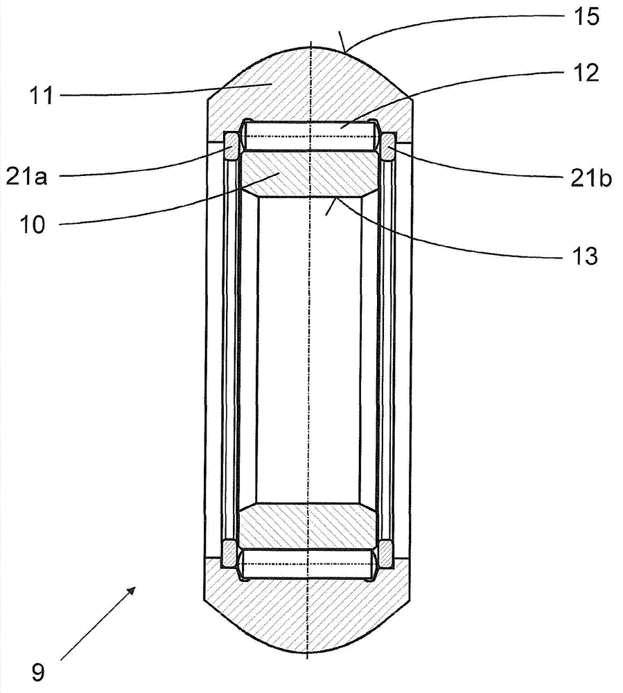
[0025] On each pin 7 of the universal joint inner part 3 there are arranged figure 2 shown separately in and in figure 1The three-pin roller 9 shown in an enlarged cross-sectional view has an inner roller ring 10 , an outer roller ring 11 and a plurality of cyli...


PUM


Abstract

The invention relates to a tripod constant velocity joint, having an outer joint part (2) which has a central cavity (4) and three openings (5) originating therefrom and arranged in an equally distributed manner around the circumference, each opening having two axially parallel guide tracks (6a, 6b) that are parallel and opposite one another around the circumference, wherein said joint also has an inner joint part (3), which is arranged within the cavity in the outer joint part and has three pins (7) having a spherical outer contour (8) and arranged in an equally distributed manner around the circumference, each pin projecting radially into one of the openings of the outer joint part, and said joint additionally has three tripod rollers (9) each having a roller inner ring (10), a roller outer ring (11) and a plurality of cylindrical rolling bodies (12); arranged annularly between the roller rings. The inner wall (13) of each inner ring (10) is in sliding contact with the outer contour of the associated pin (7), and the outer wall (15) of the each roller outer ring (11) is in sliding contact with the guide tracks (6a, 6b) of the associated opening (5). The frictional and wear properties of the constant velocity joint (1) are improved by means of a suitable surface treatment of each of the walls (8,13;6a,6b,15) that are in sliding contact with another component.

Description

technical field [0001] The invention relates to a three-pin constant velocity universal joint with an outer part of the universal joint, an inner part of the universal joint and three three-pin rollers. , recesses arranged evenly distributed on the peripheral side, each having two axis-parallel guide rails parallel to each other on the peripheral side, the inner part of the universal joint is arranged in the hollow space of the outer part of the universal joint and There are three pins with a spherical outer contour that are arranged evenly distributed on the peripheral side and each protrude radially into one of the recesses of the outer part of the universal joint. The tripod rollers each have an inner roller ring, an outer roller ring ring and a plurality of cylindrical rolling elements arranged in a ring between the roller rings; With its outer wall, the outer ring is in sliding contact with the guide rail of the associated recess. Background technique [0002] In an a...

Claims


Application Information

Patent Timeline
Patent Type & Authority Applications(China)
IPC IPC(8): F16D3/205
CPCF16D3/2055F16D3/24F16D2003/2026F16C33/605F16C19/46
Inventor 克里斯托夫·瓦利泽尔雷米·伯恩哈特
Owner SCHAEFFLER TECH AG & CO KG
Why Eureka
Try Eureka