Rotor
A rotor and rotor core technology, applied in the field of embedded magnet synchronous motors, can solve the problems of motor torque density reduction and achieve the effect of preventing torque density reduction
- Summary
- Abstract
- Description
- Claims
- Application Information
AI Technical Summary
Problems solved by technology
Method used
Image


Examples
no. 1 approach )
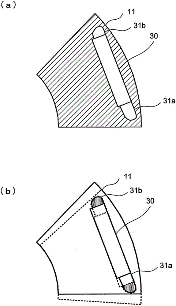
[0038] figure 1 It is an explanatory diagram of the rotor 1 according to the first embodiment of the present invention. figure 1 (A) shows a cross-sectional view of a plane perpendicular to the axial direction of the rotor 1. figure 1 (B) means figure 1 (A) A-A section view.
[0039] The rotor 1 is configured by inserting permanent magnets 20 into magnet holes 30 formed in the rotor core 10.
[0040] The rotor core 10 is constituted by laminating flat plates 11 made of electromagnetic steel sheets in the axial direction (rotation axis direction of the rotor 1 ). Such as figure 1 As shown in (a), the plate 11 is respectively provided with a shaft hole 12 through which the shaft penetrates at the center portion, and the end surface of the rotor core 10 is opened at equal intervals in the circumferential direction around the shaft hole 12 and extends along The magnet hole 30 penetrates in the axial direction.
[0041] In the rotor core 10, a permanent magnet 20 is inserted into each ma...
no. 2 approach )
[0073] Next, a second embodiment of the present invention will be described.
[0074] Figure 7 and Figure 8 It is an explanatory diagram of the rotor core 10 of the second embodiment of the present invention.
[0075] In the first embodiment described above, the front and back surfaces of the plates 11 of the same shape are laminated in reverse to form different eccentric blocks 10a and 10b. In contrast, in the second embodiment, the connecting block 15 is arranged between the different eccentric blocks 10a and 10b. In addition, the same reference numerals are given to the same configuration as the first embodiment, and the description thereof is omitted.
[0076] Figure 7 (A) is an explanatory drawing of the main part of the plate 11a which comprises the eccentric block 10a. Figure 7 (B) is an explanatory diagram of the main part of the plate 11b constituting the connection block 15. Figure 7 (C) is an explanatory drawing of the main part of the plate 11a which comprises the e...
no. 3 approach )
[0085] Next, a third embodiment of the present invention will be described.
[0086] Picture 9 It is an explanatory diagram of the rotor core 10 of the third embodiment of the present invention.
[0087] Picture 9 (A) is a perspective view of the permanent magnet 21 of the third embodiment. Picture 9 (B) Represents the rotor core 10 figure 1 (A) A-A section view. In addition, the same reference numerals are given to the same configurations as those of the first embodiment, and the description thereof is omitted.
[0088] In the third embodiment, by carefully designing the shape of the permanent magnet 21, the gap 31 is communicated between the different eccentric blocks 10a and 10b.
[0089] Specifically, such as Picture 9 As shown in (a), a notch 25 is formed in a portion orthogonal to the surface 22 on one end side in the circumferential direction on a surface horizontal to the axial direction of the permanent magnet 21 and a surface 23 on one end side perpendicular to the a...
PUM
 Abstract
Description
Claims
Application Information
 - R&D
- Intellectual Property
- Life Sciences
- Materials
- Tech Scout
- Unparalleled Data Quality
- Higher Quality Content
- 60% Fewer Hallucinations
Browse by: Latest US Patents, China's latest patents, Technical Efficacy Thesaurus, Application Domain, Technology Topic, Popular Technical Reports.
© 2025 PatSnap. All rights reserved.Legal|Privacy policy|Modern Slavery Act Transparency Statement|Sitemap|About US| Contact US: help@patsnap.com