
Wireless power supply system used for printed circuit boards

A printed circuit board and wireless power supply technology, which is applied to printed circuit components, electromagnetic wave systems, circuit devices, etc., can solve problems such as complex wiring, poor power supply quality, and poor anti-interference ability of printed circuit boards, and achieve simplified wiring , save board space, improve the effect of anti-interference ability

Inactive Publication Date: 2013-04-03
HARBIN INST OF TECH
View PDF4 Cites 13 Cited by
  • Summary
  • Abstract
  • Description
  • Claims
  • Application Information

AI Technical Summary

Problems solved by technology

[0003] The present invention aims to solve the problems of complex routing, poor power supply quality, and poor anti-interference ability of printed circuit boards caused by the existing power supply method using external power lines, thereby providing a wireless power supply system for printed circuit boards

Method used


Image

  • Wireless power supply system used for printed circuit boards
  • Wireless power supply system used for printed circuit boards

Examples


specific Embodiment approach 1

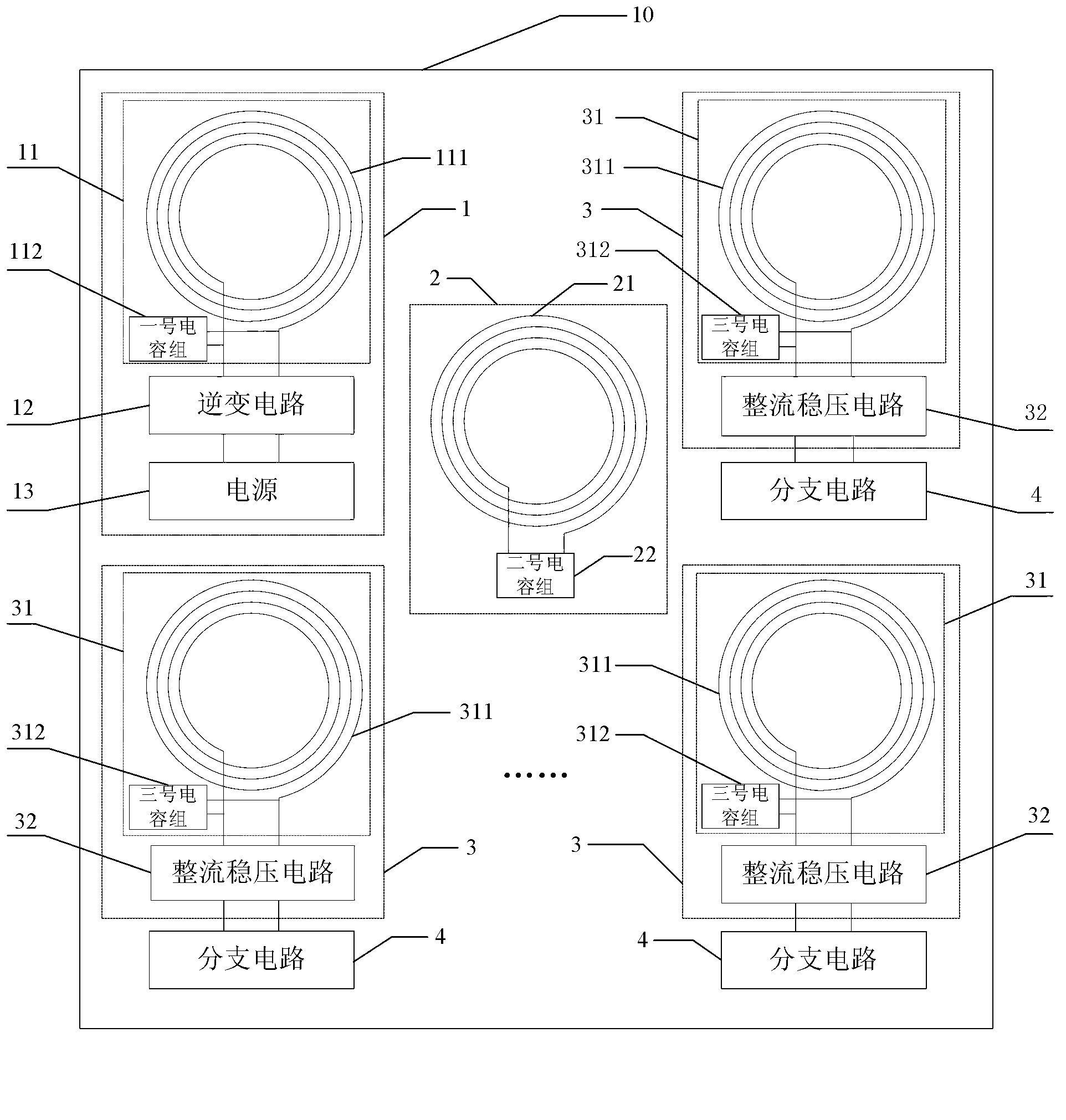
[0022] Specific implementation mode 1. Combination figure 1 Describe this specific embodiment, a wireless power supply system for a printed circuit board, which includes a transmitting circuit 1 and n receiving circuits 3; the transmitting circuit 1 and n receiving circuits 3 are both arranged on the printed circuit board 10; n is positive integer;

[0023] The transmitting circuit 1 is used to invert direct current into alternating current with frequency f, and emit an alternating magnetic field with frequency f;

[0024] Each receiving circuit 3 is used for inducing the alternating magnetic field generated by the transmitting circuit 1, and generating alternating current with a frequency f, and the alternating current is rectified and stabilized to supply power to a branch circuit.

[0025] In this embodiment, the No. 1 coil and the No. 1 capacitor group, and the No. 3 coil and the No. 3 capacitor group may also be connected in series.

[0026] When the branch circuits do ...

specific Embodiment approach 2

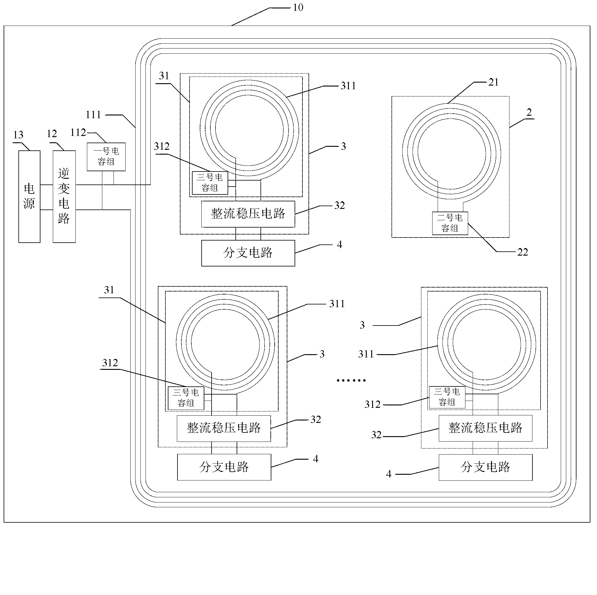
[0037] Embodiment 2. The difference between this embodiment and the wireless power supply system for printed circuit boards described in Embodiment 1 is that it further includes M relay circuits 2; the relay circuits 2 are arranged on the printed circuit on board 10;

[0038] The relay circuit 2 is used for inducing the alternating magnetic field generated by the transmitting circuit 1 and resonating, improving the waveform and increasing the formed resonant current, thereby enhancing the strength of the alternating magnetic field and ensuring that each receiving circuit 3 can receive the alternating magnetic field. Variable magnetic field; M is a positive integer.

specific Embodiment approach 3

[0039] Embodiment 3. The difference between this embodiment and the wireless power supply system for printed circuit boards described in Embodiment 2 is that the transmitter circuit 1 includes a resonant transmitter circuit 11, an inverter circuit 12 and a power supply 13; The transmitting circuit 11 includes a No. 1 coil 111 and a No. 1 capacitor group 112;

[0040] The power supply 13 is used to provide DC power to the inverter circuit 12; the two output ends of the inverter circuit 12 are respectively connected to both ends of the first coil 111; the first capacitor group 112 is connected in parallel or in series with the first coil 111.


PUM


Abstract

The invention discloses a wireless power supply system used for printed circuit boards, relates to the field of wireless electric energy transmission, and solves the problems of complicated routing and poor power supply quality which are caused by existing power supply modes adopting externally connected power lines, and poor anti-jamming capability of the printed circuit boards. A transmitter circuit of the wireless power supply system used for printed circuit boards is used for inverting direct current into alternating current with an f frequency and sending out an alternating magnetic field with the f frequency; each receiving circuit is used for sensing the alternating magnetic field generated by the transmitter circuit and generating alternating current with the f frequency; and the alternating current is performed with rectification and voltage stabilization and then supplies power for a branch circuit. The wireless power supply system used for printed circuit boards is suitable for wireless power supply of printed circuit boards.

Description

technical field [0001] The present invention relates to the field of wireless power transmission. Background technique [0002] There are often several circuits on a printed circuit board, and the power supply of these circuits comes from the power lines drawn from the power circuit. When there are many power branches on a circuit board, the traces become more complicated and take up more space on the printed circuit board. In addition, in actual use, such as relays, high-frequency switching circuits, etc., will increase the power supply ripple, affect the quality of the power supply, and thus affect the work of other circuits. In order to reduce mutual interference between different circuits, some branch circuits are often electrically isolated. The traditional isolation method mainly uses an isolated power supply, but the cost of the isolated power supply is high, and because of the transformer inside, the volume is large. SUMMARY OF THE INVENTION [0003] The inventi...

Claims


Application Information

Patent Timeline
Patent Type & Authority Applications(China)
IPC IPC(8): H02J17/00H05K1/02H05K1/16H02J50/12
Inventor 朱春波郭尧逯仁贵魏国
Owner HARBIN INST OF TECH
Learn More