
Energy-saving device and method for dynamic reactive power compensation of pumping unit

An energy-saving device and pumping unit technology, applied in the direction of reactive power compensation, reactive power adjustment/elimination/compensation, etc., can solve the problems of power system grid harmonic pollution, serious output harmonics, harmonic pollution, etc., to achieve harmonic Low wave content, reduced power loss, and improved power factor

Active Publication Date: 2016-04-20
河南费曼电力技术有限公司
View PDF2 Cites 0 Cited by
  • Summary
  • Abstract
  • Description
  • Claims
  • Application Information

AI Technical Summary

Problems solved by technology

The frequency conversion device of this topology usually adopts the method of energy consumption and resistance consumption for the "reverse power generation" of the motor caused by the unbalanced operation of the beam pumping unit, but this method will not only generate a lot of harmonic pollution, The output harmonics are relatively serious, which brings harmonic pollution to the power system grid, and at the same time causes a lot of energy waste

Method used


Image

  • Energy-saving device and method for dynamic reactive power compensation of pumping unit
  • Energy-saving device and method for dynamic reactive power compensation of pumping unit
  • Energy-saving device and method for dynamic reactive power compensation of pumping unit

Examples


Embodiment Construction

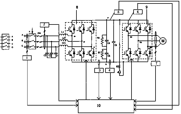
[0017] Such as figure 1 As shown, the energy-saving device for dynamic reactive power compensation of the pumping unit of the present invention includes a data acquisition control unit 10, a voltage acquisition unit, a current acquisition unit, a rectification unit 8, and an inverter unit 9, and the grid voltage passes through the filter circuit (capacitors C1, C2, C3 and reactors L1, L2, L3) are connected to the input end of the rectification unit 8, the output end of the rectification unit 8 is connected to the input end of the inverter unit 9, and the output end of the inverter unit 9 is connected to the motor M of the pumping unit The power terminal is connected; the rectification unit 8 uses six power electronic devices IGBT to form a three-phase rectifier bridge, and the two ends of each IGBT are connected in parallel with freewheeling diodes; the inverter unit 9 uses six power electronic devices The IGBT constitutes a three-phase inverter bridge, wherein freewheeling di...


PUM


Abstract

The invention discloses a device for dynamic reactive power compensation energy saving of an oil pumping unit. The device comprises a data collection control unit, voltage collection units, current collection units, a rectifying unit and an inversion unit. Power grid voltage is connected with the input end of the rectifying unit through a filtering circuit, the output end of the rectifying unit is connected with the input end of the inversion unit, the output end of the inversion unit is connected with the power supply end of a motor of the oil pumping unit, and the signal control ends of the rectifying unit and the inversion unit are connected with the driving signal output end of the data collection control unit respectively. The device is further provided with the voltage collection units and the current collection units, the signal output ends of the current collection units and the voltage collection units are connected with the signal input end of the data collection control unit, and the data collection control unit is further provided with a voltage zero passage signal detection system. The device can compensate reactive power of impact load, balances three-phase active current, enables the oil pumping unit to continuously pump oil, enables the oil pumping unit to run in intermittently or in frequency reducing mode according to oil quantity and automatically adjust pumping speed, improves power factor and reduces power loss.

Description

technical field [0001] The invention relates to a reactive power compensation energy-saving device, in particular to a dynamic reactive power compensation energy-saving device and method for adjusting a pumping unit. Background technique [0002] At present, the electrical part of the pumping unit is mainly composed of a three-phase asynchronous motor and a control circuit. The motor drives the sucker rod to reciprocate, pumping crude oil continuously from the ground to the ground, and the load of the pumping unit is The stroke is a cyclical load with a continuously changing period. When the sucker rod is lowered, the load is very light, which is equivalent to no load, but when it is raised, the crude oil is pumped out of the ground, so the load is very heavy, which is equivalent to a full load. Therefore, the load of the pumping unit is constantly changing, and the changing cycle is also very short. The load changes twice in each stroke, and the heavy-duty working time is ...

Claims


Application Information

Patent Timeline
Patent Type & Authority Patents(China)
IPC IPC(8): H02J3/18
CPCY02E40/30
Inventor 武伟伟龙翔陆继明杨继兵
Owner 河南费曼电力技术有限公司
Learn More