
Full-airspace-covering high-gain circularly polarized antenna

A circularly polarized antenna and high-gain technology, which is applied in the field of ground circularly polarized transmitting antennas, can solve the problems that the elevation angle cannot reach 0°, the gain cannot meet the use requirements, and the tracking and measurement and control cannot be met, so as to solve the problems of high-power transmission, Excellent low elevation fluctuation and wide-angle circular polarization axial ratio characteristics, the effect of reducing output power requirements

Inactive Publication Date: 2013-04-03
BEIJING RES INST OF TELEMETRY +1
View PDF4 Cites 13 Cited by
  • Summary
  • Abstract
  • Description
  • Claims
  • Application Information

AI Technical Summary

Problems solved by technology

However, the maximum gain direction of these antennas is at an elevation angle of 90° (axial), and the gain in the area near the elevation angle of 0° cannot meet the requirements for use.
[0006] Although the conical helix and the resonant quadrifilar helix antenna can easily realize the "saddle-shaped" pattern, the maximum radiation direction of these two antennas can only reach an elevation angle of more than 10° due to their radiation mechanism and structural limitations. However, it cannot reach the elevation angle of 0°, and cannot meet the requirements of target tracking and measurement and control in the whole airspace.

Method used


Image

  • Full-airspace-covering high-gain circularly polarized antenna
  • Full-airspace-covering high-gain circularly polarized antenna
  • Full-airspace-covering high-gain circularly polarized antenna

Examples


Embodiment Construction

[0021] The present invention will be further described below in conjunction with accompanying drawing.

[0022] Such as figure 1 , 2 As shown, the high-gain circularly polarized antenna covering the whole space of the present invention includes a shaped spherical reflector 1, an insulating support rod 2 and a four-arm helical antenna, and the shaped spherical reflector 1 is installed on the four arms through the insulating support rod 2 In front of the helical antenna.

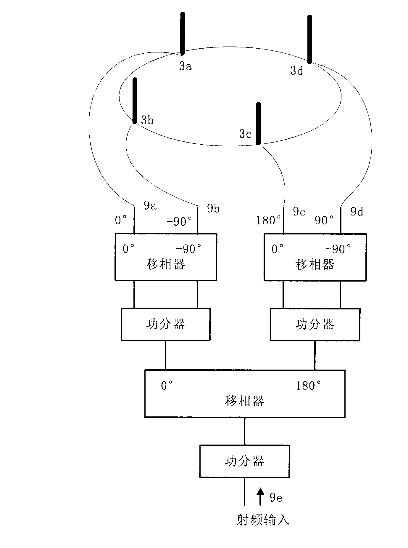
[0023] The four-arm helical antenna is a wide-beam resonant antenna, including a helical arm 3 , a short-circuit support column 4 , a metal base plate 5 , a radio frequency socket 6 , a feed network box 7 , a dielectric cover 8 and a feed network printed board 9 .

[0024] Among them, the helical arms 3 are four identical double-turn single-wound helical wires with constant diameter and constant pitch angle, and the length of the helical arms 3 is 2λ (λ is the free space wavelength). The four spiral arms 3 ...


PUM


Abstract

The invention discloses a full-airspace-covering high-gain circularly polarized antenna. The circularly polarized antenna comprises a forming spherical reflecting surface (1), an insulating support bar (2) and a four-arm helical antenna, wherein the forming spherical reflecting surface (1) is installed in front of the four-arm helical antenna through the insulating support bar (2), and the four-arm helical antenna is a wide-beam resonant antenna. The wide-beam resonant four-arm helical antenna serves as a radiator, the forming spherical reflecting surface is added, the antenna beam width is further broadened, and low elevation gains are improved, so that the maximum gain of the antenna points to the zero-degree elevation nearby, the gains decline gradually with the increasing of the elevation, a saddle-shaped radiation pattern is finally formed, the maximum gain direction is close to the horizontal direction, the zero-degree elevation gain can reach about 4.5dB which is much higher than that of an ordinary wide-beam antenna, the output power requirement for a power amplifier is greatly reduced, and actual using requirements for target tracking and measurement and control are met.

Description

technical field [0001] The invention belongs to the field of aircraft target tracking and measurement and control, and in particular relates to a ground circularly polarized transmitting antenna which needs to have maximum gain in the horizontal direction and can cover the entire upper half space. Background technique [0002] In the tracking and measurement and control of aircraft targets, the gain of the transmitting antenna of the ground measurement and control station is mainly determined by the operating distance, flight height and target angle. For a fixed flight altitude, the gain of the antenna at the lowest elevation angle is determined by the maximum operating distance, while the gain of the antenna above the lowest elevation angle has a cosecant square relationship with the elevation angle. It can be seen that in order to achieve full airspace coverage, the antenna beam width is required to be extremely wide and omnidirectional in the azimuth plane, that is, the a...

Claims


Application Information

Patent Timeline
IPC IPC(8): H01Q1/36H01Q13/08H01Q19/12H01Q21/24
Inventor 肖伟清孙向珍邓昊刘昊
Owner BEIJING RES INST OF TELEMETRY
Learn More