
A wide-beam multi-dielectric composite resonator antenna based on pattern superposition

A composite resonator and dielectric resonator technology, applied in resonant antennas, antennas, electrical short antennas, etc., can solve the problems of narrow beam width and uneven gain in the upper half space, and achieve widened beam width and superior beam equalization , to overcome the effect of narrow beam width

Active Publication Date: 2022-05-03
UNIV OF ELECTRONICS SCI & TECH OF CHINA
View PDF5 Cites 0 Cited by
  • Summary
  • Abstract
  • Description
  • Claims
  • Application Information

AI Technical Summary

Problems solved by technology

[0004] The purpose of the present invention is to provide a wide-beam multi-dielectric composite resonator antenna based on pattern superposition to solve the technical problems of the existing dielectric resonator with narrow beam width and uneven gain in the upper half space, which discretizes the dielectric resonator into Multiple dielectric resonant units are spliced ​​to form a multi-dielectric composite resonator through the differential design of the dielectric constant of each dielectric resonant unit, and the dielectric resonator is used to expand the radiation pattern of a pair of odd and even high-order modes. The antenna beam width is improved, wide beam is realized, and it has excellent beam equalization, which is suitable for the application of wide beam antenna

Method used


Image

  • A wide-beam multi-dielectric composite resonator antenna based on pattern superposition
  • A wide-beam multi-dielectric composite resonator antenna based on pattern superposition
  • A wide-beam multi-dielectric composite resonator antenna based on pattern superposition

Examples


Embodiment Construction

[0026] In order to make the object, technical solution and advantages of the present invention clearer, the present invention will be further described in detail below in conjunction with the accompanying drawings and examples.

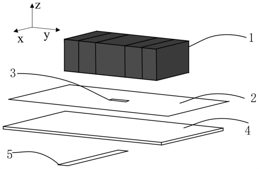
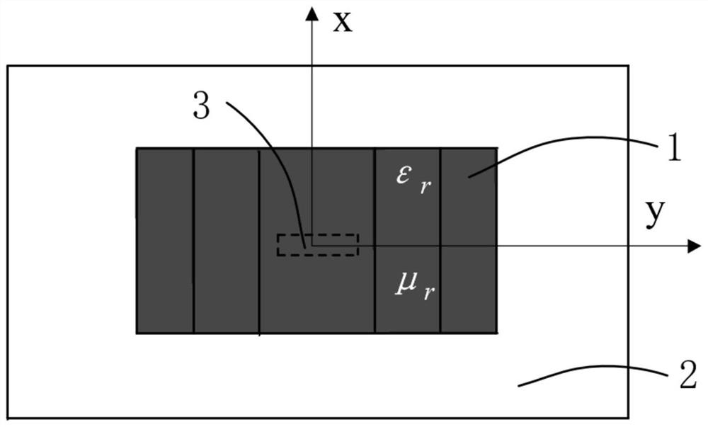
[0027] This embodiment provides a wide-beam multimedia composite resonator antenna based on pattern superposition, the structure of which is as follows Figure 1 ~ Figure 4 As shown, it specifically includes: a dielectric resonator 1, a floor 2, a feed slot 3, a dielectric substrate 4 and a feeder 5; wherein,

[0028] The floor 2 is attached and covered on the upper surface of the dielectric substrate 3, and the center of the floor is etched with a feed slot 3, the feeder 5 is arranged on the lower surface of the dielectric substrate 3, and the dielectric resonator 1 is fixed on the floor 2 Surface and located in the center of the floor, the wide-beam stepped dielectric resonator antenna is fed by the feeder 5, and the electromagnetic wave energy is c...


PUM

PropertyMeasurementUnit
thicknessaaaaaaaaaa
lengthaaaaaaaaaa
widthaaaaaaaaaa

Abstract

The invention belongs to the technical field of wide-beam antennas, and specifically provides a wide-beam multi-dielectric composite resonator antenna based on pattern superposition to solve technical problems such as narrow beam width and uneven gain in the upper half of the existing dielectric resonator. In the present invention, the antenna includes: a dielectric resonator 1, a floor 2, a feed slot 3, a dielectric substrate 4 and a feed line 5, the antenna is fed by the feed line, and is coupled and conducted to the dielectric resonator on the upper surface through the feed slot on the floor; The resonator is a multi-dielectric composite resonator composed of a plurality of dielectric resonant units adjacent in sequence. The invention discretizes the dielectric resonator into a plurality of dielectric resonant units, forms a multi-dielectric composite resonator through the differential design of the dielectric constant of each dielectric resonant unit, and utilizes the radiation pattern of a pair of odd and even high-order modes of the dielectric resonator The superposition method widens the antenna beam width, realizes wide beam, and has excellent beam equalization, which is suitable for the application occasion of wide beam antenna.

Description

technical field [0001] The invention belongs to the technical field of wide-beam antennas, in particular to a wide-beam multi-media composite resonator antenna based on pattern superposition. Background technique [0002] With the rapid development of information science and technology, the signal coverage of the antenna is getting higher and higher in the fields of satellite navigation, communication and radio frequency identification, which means that the beam width of the antenna is required, and how to widen the width of the antenna is also The current research hotspots of scholars. [0003] So far, wide-beam antennas mainly include microstrip antennas, magnetoelectric dipole antennas, and helical antennas. Due to the high surface loss and conductor loss of metal antennas at high frequencies, the radiation efficiency of such antennas is relatively low. Low, it will also encounter difficulties in processing because the size is too small. Since the dielectric resonator a...

Claims


Application Information

Patent Timeline
Patent Type & Authority Patents(China)
IPC IPC(8): H01Q9/04G06F30/20
CPCH01Q9/0485G06F30/20
Inventor 潘锦杨茜麟马伯远刘贤峰杨德强
Owner UNIV OF ELECTRONICS SCI & TECH OF CHINA
Learn More