Forced diversion control method

A control method and technology at the beginning of time, applied in three-dimensional position/course control and other directions, to achieve strong engineering realization, fast flying around, and fuel consumption saving effects

Active Publication Date: 2015-05-27
BEIJING INST OF CONTROL ENG
View PDF3 Cites 0 Cited by
  • Summary
  • Abstract
  • Description
  • Claims
  • Application Information

AI Technical Summary

Problems solved by technology

[0004] The technical problem to be solved by the present invention is to provide a limited-segment-based forced circumnavigation control method to solve the problem of rapid circumnavigation control during the in-orbit service of the spacecraft to the target, which can realize rapid circumnavigation and save fuel

Method used


Image

  • Forced diversion control method
  • Forced diversion control method
  • Forced diversion control method

Examples


Embodiment Construction

[0019] Taking the tracking satellite to force the target satellite to fly around as an example, the present invention will be described based on the limited segment forced flying around control method, which specifically includes the following steps:

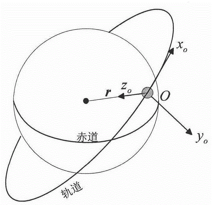
[0020] (1) Establish the target satellite orbit coordinate system

[0021] Such as figure 2 As shown, the target satellite orbit coordinate system is defined as (O-X o Y o Z o ): The coordinate origin is located at the center of mass of the target satellite, and the Z-axis points from the center of mass of the target satellite to the center of the earth within the orbital plane of the target satellite; the Y-axis is perpendicular to the orbital plane, pointing to the negative normal of the orbital plane, and the orbital momentum moment vector The directions are opposite; the X-axis and the Y-axis and Z-axis form a right-handed spiral, pointing to the direction in which the satellite is flying.

[0022] The present inventio...


PUM


Abstract

The invention discloses a forced diversion control method which includes first conducting diversion nominal track design according to a designated diversion period, conducting subsection planning on a motor-driven path based on error boundary and adopting a single pulse control method based on C-W guidance rate in each section to achieve track tracking of the subsection planning route to form a single side limit cycle. The method completely utilizes diversion largest error boundary, plans movement track in an error boundary and controlled diversion track moving tread, achieves quick diversion, saves fuel consumption and has strong engineering practicalness.

Description

technical field [0001] The invention relates to a control method for rapidly forcing a space vehicle to fly around a space target when the space vehicle performs circumvention monitoring and reconnaissance. Background technique [0002] Space vehicles flying around space targets are divided into natural flying and forced flying. Natural orbiting means that after the two aircraft satisfy a certain orbital relationship, under the action of the space perturbation force, one aircraft will fly around the other without orbit control in a short period of time. It is a natural flight state in the space environment. "Forced circling" refers to making the aircraft fly around the target with an unnatural orbital period as the circling period through orbit control. This kind of circling destroys the natural flight state in the space environment through orbit control. For a slow-spinning target, if the angular velocity of the aircraft is equal to the angular velocity of the slow-spinnin...

Claims


Application Information

Patent Timeline
Patent Type & Authority Patents(China)
IPC IPC(8): G05D1/10
Inventor 李克行何英姿魏春岭曾海波刘潇翔黎康朱志斌汤亮熊凯谈树萍
Owner BEIJING INST OF CONTROL ENG
Why Eureka
Try Eureka