Rotary-motion-oriented reed type linear micro-driving mechanism

A rotary motion, reed-type technology, applied in installation, optics, instruments, etc., can solve the problem that the best matching angle of the crystal is not easy to adjust, and achieve the advantages of convenient debugging and maintenance, simple structure, high reliability and stability Effect

Active Publication Date: 2014-12-17
HARBIN INST OF TECH
View PDF6 Cites 0 Cited by
  • Summary
  • Abstract
  • Description
  • Claims
  • Application Information

AI Technical Summary

Problems solved by technology

[0003] The purpose of the present invention is to provide a reed-type linear micro-drive mechanism for rotary motion to solve the problem of difficult adjustment of the optimal matching angle of the crystal in the electric mirror module and the frequency conversion module in the photoelectric control system of the inertial-constrained laser nuclear fusion device To achieve the collimation and guidance of the large-aperture laser beam and the near-field adjustment of the beam, as well as the laser frequency conversion

Method used


Image

  • Rotary-motion-oriented reed type linear micro-driving mechanism
  • Rotary-motion-oriented reed type linear micro-driving mechanism
  • Rotary-motion-oriented reed type linear micro-driving mechanism

Examples


specific Embodiment approach 1

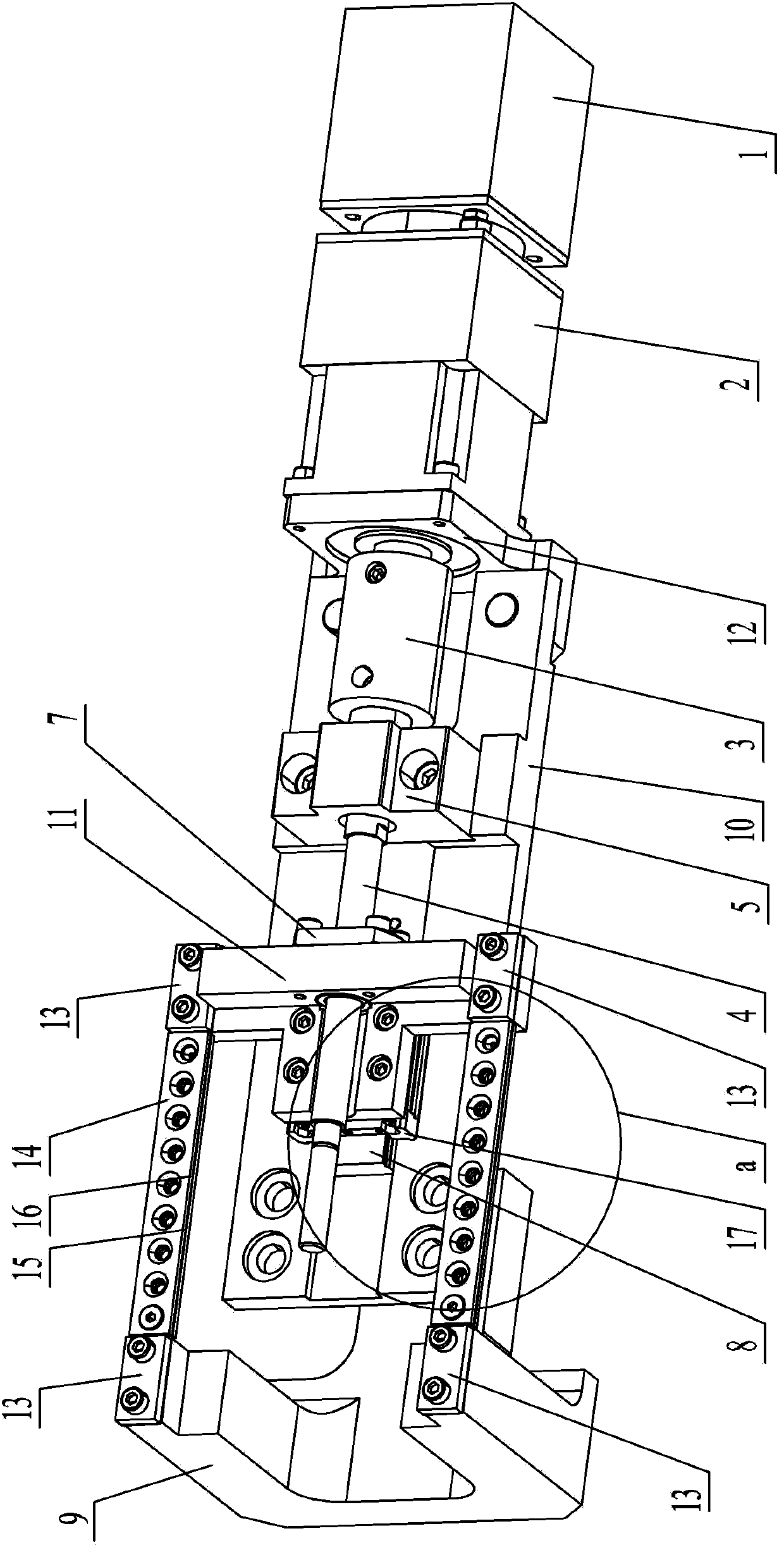
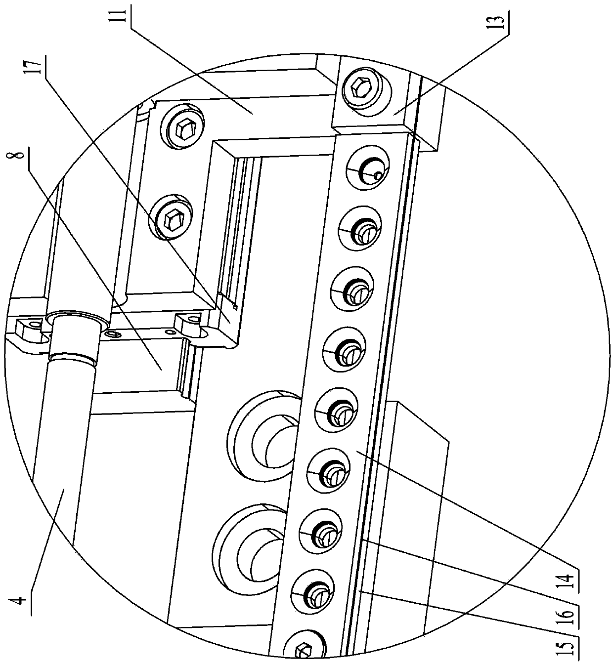
[0010] Specific implementation mode one: combine Figure 1 to Figure 3 Describe this embodiment, a reed type linear micro-drive mechanism for rotary motion in this embodiment includes a stepper motor 1, a reducer 2, a rigid coupling 3, a rolling screw 4, a bearing seat 5, and a rolling bearing assembly 6 , rolling nut 7, connecting block 9, base 10, nut seat plate 11, base bending plate 12, rolling guide rail 8, slider 17, four reed pressure plates 13, two upper splints 14, two lower splints 15 , two reeds 16;

[0011] The output shaft of the stepping motor 1 is connected to the reducer 2, and the side wall on the output side of the reducer 2 is installed with a base bending plate 12, and the output shaft of the reducer 2 passes through the base bending plate 12 and passes through the rigid coupling The device 3 is connected with one end of the rolling screw 4, the base 10 is installed on the base curved plate 12, the rolling guide rail 8 and the bearing housing 5 are install...

specific Embodiment approach 2

[0012] Specific implementation mode two: combination figure 1 The present embodiment will be described. The speed reducer 2 of the present embodiment is a planetary speed reducer. Other compositions and connections are the same as in the first embodiment.

[0013] The linear micro-drive mechanism can convert linear motion into rotary motion through the connection with the connecting block, the adjustment range of the rotary motion is ±15mrad, and the adjustment accuracy is better than 5urad. The micro-drive mechanism is mainly used to drive the rotary motions such as pitch and yaw of the optical lens.


PUM


Abstract

The invention relates to a rotary-motion-oriented reed type linear micro-driving mechanism, in particular to a linear micro-driving mechanism. The linear micro-driving mechanism aims to solve the problems that the optimal matching angles of crystals in an electric reflector module and a frequency conversion module are difficult to adjust in a photoelectric control system of an inertial confinement laser nuclear fusion device. A stepper motor is connected with a speed reducer; the speed reducer is provided with a base bending plate and is connected with a rolling screw rod; the base bending plate is provided with a base; the base is provided with a rolling guide rail and a bearing block; a sliding block is arranged on the rolling guide rail; the sliding block is provided with a nut base plate; a rolling nut is arranged on the nut base plate; the rolling screw rod passes through the bearing block and is in threaded connection with the rolling nut; two reeds are horizontally arranged in parallel; each reed is clamped through an upper clamp plate and a lower clamp plate; the left end of each reed is fixedly connected to a connecting block through a reed pressing plate, and the right end of the reed is connected to the nut base plate through a reed pressing plate; and the connecting block is connected with a lens frame. The linear micro-driving mechanism is used for driving optical lenses to do rotary motion such as pitching and deflecting.

Description

technical field [0001] The invention relates to a linear micro-drive mechanism, in particular to a reed-type linear micro-drive mechanism facing rotary motion, which belongs to the technical field of mechanical drive. Background technique [0002] In the inertial confinement laser fusion device, in order to realize the precise guidance of the transmission direction of the large-diameter laser beam above 400mm and the frequency conversion of the laser beam, electric mirrors and frequency conversion devices are required. These devices require high adjustment accuracy of the optical crystal angle , The adjustment range is large, which puts forward high-precision and large-stroke requirements for the micro-drive mechanism oriented to rotary motion. The linear micro-actuation mechanism can meet the drive control requirements of high precision and large stroke, but the existing linear micro-actuation mechanism has low precision when converted to rotary motion, while the flexible h...

Claims


Application Information

Patent Timeline
Patent Type & Authority Patents(China)
IPC IPC(8): G02B7/198
Inventor 梁迎春于福利张鹏卢礼华
Owner HARBIN INST OF TECH
Why Eureka
Try Eureka