
Sensor with permanent depth marks on connecting wires

A technology for connecting wires and sensors, which is applied in the field of sensors, can solve the problems of fading, hard to identify, easy to wear, etc., and achieve the effects of improving measurement accuracy, enhancing water resistance, and being convenient to use

Inactive Publication Date: 2013-04-03
陈彦平
View PDF6 Cites 0 Cited by
  • Summary
  • Abstract
  • Description
  • Claims
  • Application Information

AI Technical Summary

Problems solved by technology

[0002] When carrying out engineering geophysical prospecting or testing in the downhole, in the pipe or in the borehole, the depth needs to be measured at the same time. However, the previous depth marking is directly marked on the surface of the outer jacket (sheath) of the wire, which is easy to wear and is also subject to acid and alkali corrosion. And the impact of solvent cleaning, after a certain period of time, it will fade away and it is difficult to identify
Therefore, some directly add a collar on the wire as a mark, but this is easy to shift or fall off, and also affects the accurate measurement of the taxi wheel
Some also arrange another dedicated depth scale in parallel next to the wire, but it is extremely inconvenient to use

Method used


Image

  • Sensor with permanent depth marks on connecting wires
  • Sensor with permanent depth marks on connecting wires
  • Sensor with permanent depth marks on connecting wires

Examples


Embodiment 1

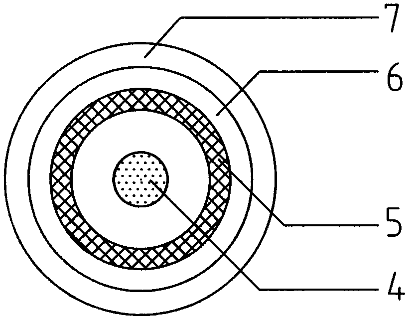
[0017] as attached figure 1 , attached figure 2 And attached image 3 As shown, an ultrasonic transducer with a permanent depth mark on the connecting wire. This example is an ultrasonic transducer shared by sending and receiving. The design uses a single-core coaxial shielded wire. For materials, print digital depth markings in decimeters every 10 centimeters on the surface of the quilt, such as the marking of 99.7m long connecting wires, starting from the top of the sensor as the first integral decimeter to 997 decimeters According to the corresponding depth, the numbers 3, 4, 5 ... 996, 997, etc. are spray printed, and then wrapped on the middle quilt with a transparent PVC-based outer quilt.

Embodiment 2

[0019] as attached Figure 4 As shown, an ultrasonic transducer with a permanent depth mark on the connecting wire. This example is an ultrasonic receiving transducer with a preamplifier. The design uses a three-core shielded wire, and the meter is used as the unit of measurement on the surface of the quilt. Print the digital depth mark, and then wrap the outer jacket with transparent PVC as the base material on the inner jacket.

[0020] All the other are with embodiment 1.

Embodiment 3

[0022] as attached Figure 5 Shown is a geophone with permanent depth markings on the connecting wires. The design adopts single-core coaxial shielded wire, and the center of the cable sheath is made of polyurethane base material. Every 25 cm, the digital depth mark is printed in centimeters, and then covered with a transparent polyurethane transparent film.

[0023] All the other are with embodiment 1.


PUM


Abstract

The invention relates to a sensor which requires depth measurement when being applied to geophysical prospecting or detection under a shaft, in a pipe or in a drill hole. The sensor is characterized in that a connecting wire is provided with a middle coat and an outer coat, digital depth marks are formed on the surface of the middle coat through spray printing, a layer of transparent outer coat is wrapped on the middle coat, and an isolation protection effect is achieved through the transparent outer coat, so that the sensor is wear resistant and cannot be influenced by acid-base corrosion and solvent cleaning, and the depth marks are ensured to be clear after the sensor is used for a long time. The sensor is used for performing engineering geophysical prospecting and detection, and comprises an ultrasonic transducer, a hydrophone, a wave detector, a resistivity sensor, a magnetic induction sensor and the like.

Description

Technical field [0001] The invention relates to a sensor that needs to measure depth when it is used in downhole, in a pipe or in a borehole for geophysical exploration or detection. Background technique [0002] When carrying out engineering geophysical prospecting or testing in the downhole, in the pipe or in the borehole, the depth needs to be measured at the same time. However, the previous depth marking is directly marked on the surface of the outer jacket (sheath) of the wire, which is easy to wear and is also subject to acid and alkali corrosion. And the impact of solvent cleaning, after a certain period of time, it will fade away and it is difficult to identify. So some directly add the collar on the wire as a mark, but it is easy to shift or fall off like this, which also affects the accurate measurement of the taxi wheel. Also have another special-purpose depth gauge to be arranged in parallel next to the wire, but it is extremely inconvenient to use. Contents o...

Claims


Application Information

Patent Timeline
Patent Type & Authority Applications(China)
IPC IPC(8): G01B21/18
Inventor 陈彦平陈准
Owner 陈彦平
Learn More