
Three-level multi-spray-pipe central ejector

A multi-nozzle and ejector technology, used in jet pumps, machines/engines, non-displacement pumps, etc., can solve the problems of difficulty in complete mixing, large ejection airflow, and difficult processing, and shorten the length of the mixing chamber. , the effect of increasing the suction capacity and being easy to process and manufacture

Active Publication Date: 2013-04-03
CHINA ACAD OF AEROSPACE AERODYNAMICS
View PDF6 Cites 9 Cited by
  • Summary
  • Abstract
  • Description
  • Claims
  • Application Information

AI Technical Summary

Problems solved by technology

However, compared with the multi-nozzle central ejector, the friction loss per unit length of the mixing chamber of the annular ejector is large, and the mixing process of the ejected airflow and the ejected airflow is relatively slow, resulting in a large structure size and low mixing efficiency.
Especially for large-scale wind tunnels, the disadvantages of annular ejectors become more obvious
The flow rate of the ejected airflow in a large-sized wind tunnel is large, and the corresponding flow area is large. The center of the ejected airflow is not easily affected by the ejected airflow. The complete mixing of the two airflows is difficult and the mixing efficiency is low.
Moreover, in terms of structure, the length of the mixing chamber of the annular ejector must be lengthened, resulting in a huge structure of the annular gas collection chamber, and the corresponding pressure-bearing flanges and other components are not easy to process, etc.

Method used


Image

  • Three-level multi-spray-pipe central ejector
  • Three-level multi-spray-pipe central ejector
  • Three-level multi-spray-pipe central ejector

Examples


Embodiment Construction

[0034] The principles and features of the present invention will be described in detail below in conjunction with the accompanying drawings.

[0035] When multi-stage multi-nozzle central ejectors are connected in series, since the airflows of multi-nozzle central ejectors at all levels will affect each other, simply connecting multiple multi-nozzle central ejectors in series cannot improve the air flow rate. The pumping performance of the hole, and if the ejection parameters and structure do not match, the ejection performance will be degraded. The three-stage multi-nozzle central ejector of the present invention adopts the ejection parameters shown in Table 1 that match the structure, which greatly improves the suction performance of the wind tunnel.

[0036] Table 1

[0037]

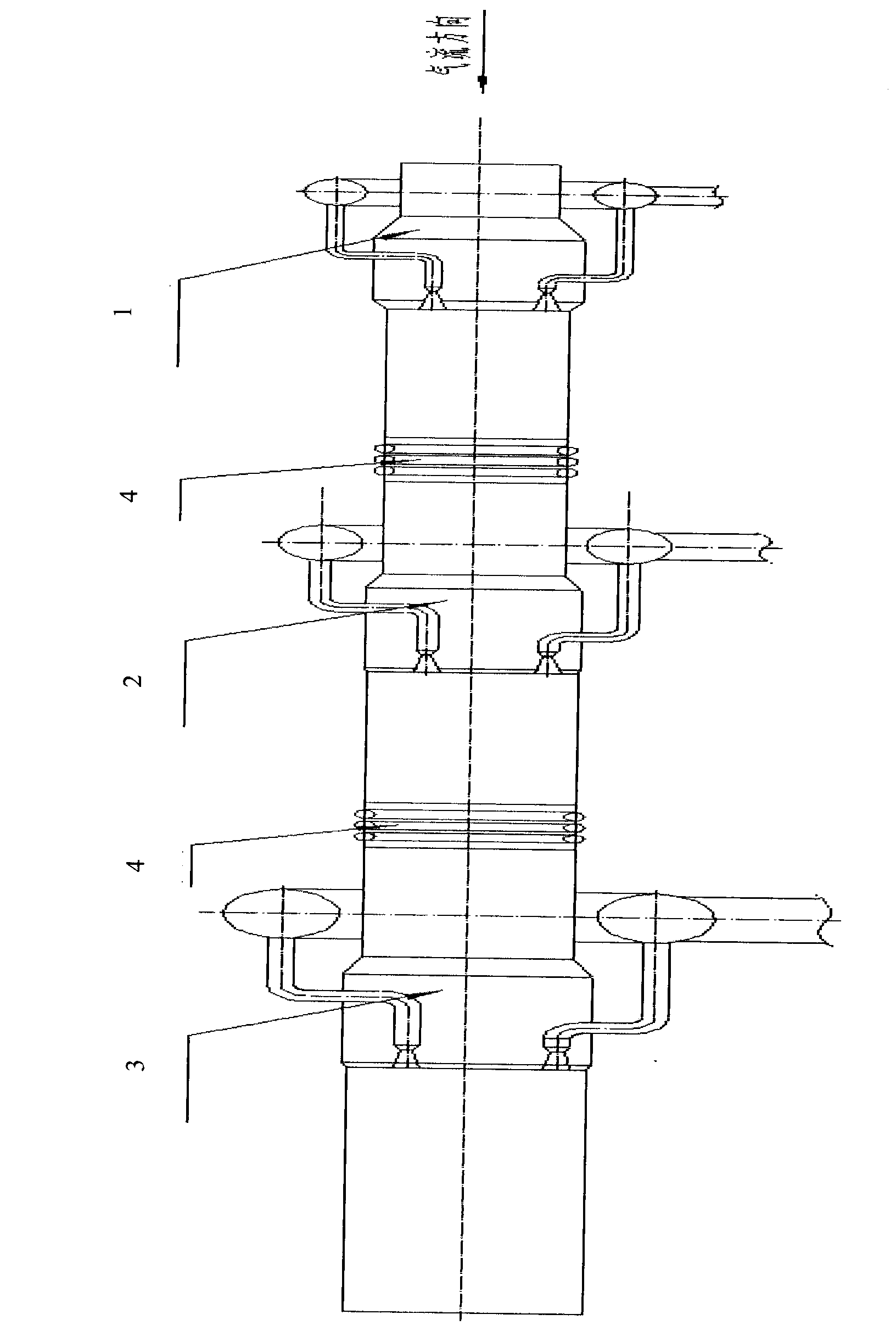
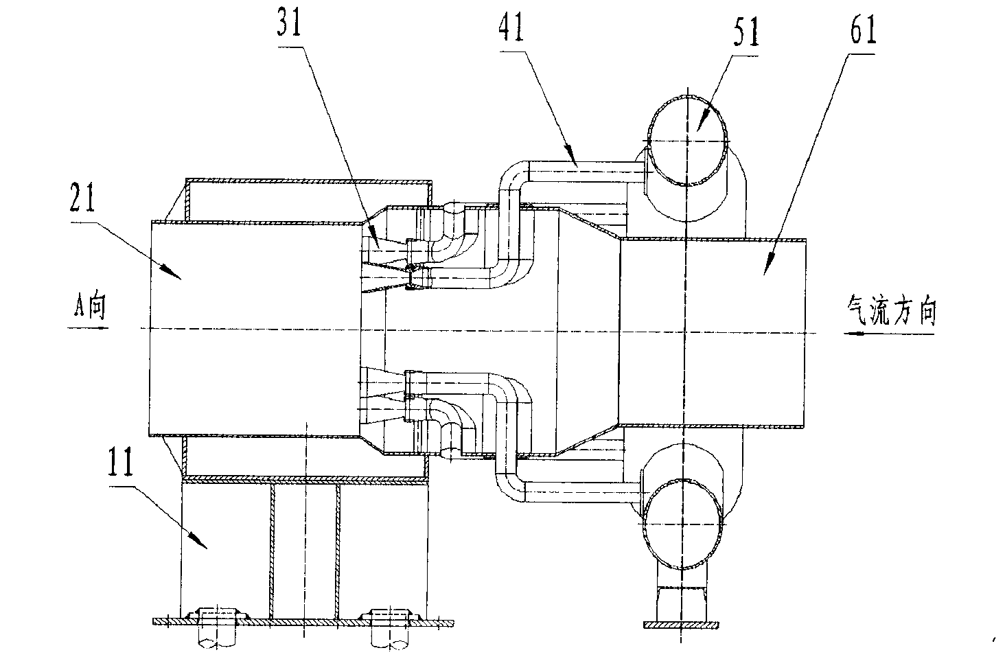
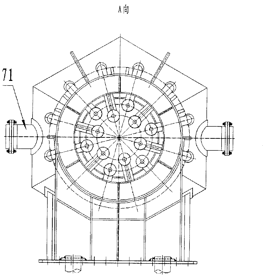
[0038] Such as figure 1 As shown, the three-stage multi-nozzle central ejector includes: a first-stage multi-nozzle central ejector 1 , a second-stage multi-nozzle central ejector 2 , and a third...


PUM

PropertyMeasurementUnit
The inside diameter ofaaaaaaaaaa

Abstract

The invention discloses a three-level multi-spray-pipe central ejector, which comprises a first-level multi-spray-pipe central ejector (1), a second-level multi-spay-pipe central ejector (2) and a third-level multi-spray-pipe central ejector (3), wherein the first-level multi-spray-pipe central ejector (1), the second-level multi-spray-pipe central ejector (2) and the third-level multi-spray-pipe central ejector (3) are sequentially connected with one another in serial along the flowing direction of main airflow, and an expansion joint (4) is respectively arranged between the first-level multi-spray-pipe central ejector and the second-level multi-spray-pipe central ejector and between the second-level multi-spray-pipe central ejector and the third-level multi-spray-pipe central ejector. The three-level multi-spray-pipe central ejector has the advantages of good pumping effect and convenience in machining and manufacturing.

Description

technical field [0001] The invention relates to a multi-stage ejector, in particular to a three-stage multi-nozzle central ejector. Background technique [0002] The ejector is a kind of gas machine, which usually consists of the following four parts: the ejector nozzle, the ejected air duct, the mixing chamber, and the diffusion section. It relies on the action of a high-pressure airflow to increase the total pressure of the low-pressure airflow, and transfer energy from one airflow to another through turbulent mixing. Specifically, the ejected airflow with a high total pressure comes out of the nozzle at a high speed and enters the mixing chamber, and forms a low static pressure at the front of the mixing chamber, and the ejected airflow that is always depressed at the front of the mixing chamber When the two airflows flow along the mixing chamber, turbulent mixing occurs, and part of the kinetic energy of the ejected airflow is transferred to the ejected airflow. As a re...

Claims


Application Information

Patent Timeline
IPC IPC(8): F04F5/22
Inventor 贾英胜孙勇堂王铁进崔春沈逢京黄景博卜俊辉石运军王凯文许瑞峰
Owner CHINA ACAD OF AEROSPACE AERODYNAMICS
Learn More